PIN MUST BE IN END OF
DESIRED UNLOADING ONLY.
INSERT PIN UNTIL FLUSH.
TURN CLOCKWISE UNTIL LOCKED.
INSERT QUICK PIN TO
LOCK IN POSITION.
31300
LOCKED
POSITION
UNLOCKED
POSITION
REAR DOOR LOCKS
Located on the inside of the left and right hand rear drive shaft brackets
are the rear door locks. These locks should be locked up against rear door
frame when forage box is being unloaded toward the front. (LOCK BEFORE
LOADING). Door locks must be unlocked (down position) when forage box
is being unloaded toward the rear. (UNLOCK BEFORE LOADING).
FAILURE TO UNLOCK REAR DOOR LOCKS WHEN BOX IS BEING
UNLOADED TO THE REAR WILL RESULT IN SEVERE DAMAGE TO THE
FORAGE BOX.
DOOR LOCK
REAR DOOR LATCHES
Located at the bottom left and right hand side of the rear door are the door
latches. These latches lock against knurled gears on rear drive shaft to
hold door closed when operating forage box as a rear unload. When tractor
hydraulics are activated and rear drive shaft turns, knurled gears flip latches
open to allow rear door to swing free. Upon completion of unloading check
rear door to insure that door latches are securely in place for next load.
DOOR LATCH
KNURLED GEAR
FIELD OPERATION OF FRONT / REAR
UNLOAD FORAGE BOX
Read and understand operator’s manual before placing unit into opera-
tion. Check entire unit carefully before operating.
SET-UP
To operate this forage box as a rear unload, the following steps must
be followed:
1. Remove clip pin (PB190) holding drive pin (PB191) in front drive
sprocket assembly. Rotate pin counter-clockwise and remove from
assembly. Re-insert drive pin into rear drive sprocket. Rotate pin clock-
wise until it locks into groove on peg. Secure with clip pin.
2. Adjust rear chain tightener so there is slight deflection at the center
of chain.
3. Unlock rear door locks located on the inside of the left and right hand
rear drive shaft brackets. CAUTION: Rear door locks should be locked
in position only when using front unload. While operating rear unload,
rear door locks MUST remain unlocked. (See Above).
4. Attach hydraulic hoses to the couplers on the front unloading unit.
5. Make sure all adjustments have been made and machine is properly
lubricated per operator’s manual prior to operation.
6. Replace and properly secure all safety shields.
7. Prior to filling forage box, connect hydraulic hoses from forage box to
the tractor. Operate rear unload to insure rear door is opening properly
and drive mechanism operates properly.
-18-
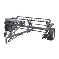
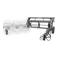
FIGURE 7
INDUSTRIAL 2-WAY UNLOAD
BOX COMPONENTS
-43-
ITEM PART NO. DESCRIPTION
ALUMINIZED SIDES
16 FT 18 FT 20 FT
1. IFB48 IFB49 IFB50 Main Frame
2. PB111 “ “ Taillight Mount
3. IFB27 “ “ Filler Corner
4. IFB53 “ “ Top Rear Brake
5. IFB54 “ “ Cross Front Brake
6. IFB125 “ “ LH Rear Stake
7. IFB126 “ “ RH Rear Stake
8. IFB127 “ “ Front Stake
9. IFB93 IFB91 IFB63 LH Top Rail
10. IFB105 IFB103 IFB101 Expanded Metal Screen LH
* IFB106 IFB104 IFB102 Expanded Metal Screen RH
11. IFB94 IFB92 IFB64 RH Top Rail
12. IFB99 IFB97 IFB95 LH Top Angle
13. IFB100 IFB98 IFB96 RH Top Angle
14. IFB124 “ “ Side Stake
NOTE: * (Means Not Shown)