EasyManua.ls Logo

Hangar 9 fokker D.VII User Manual

Hangar 9 fokker D.VII
56 pages
To Next Page IconTo Next Page
Page #1 background imageLoading...
Page #1 background image
Wingspan .....................................64.6 in (1641mm)
Length ..........................................49.8 in (1265mm)
Wing Area (Total) ..................1114 sq in (72 sq dm)
Wing Area (Top Wing) .............689 sq in (44 sq dm)
Wing Area (Bottom Wing) .......425 sq in (27 sq dm)
Wing Loading .......................................17.5 oz/sq ft
Assembly mAnuAl
Fokker D.VII
Flying Weight ...................... 8.5–9.5 lb (3.9–4.3 kg)
Engine Size ..................... .61 2-stroke, .82 4-stroke
Motor Size .................................................Power 60
Radio.........................................................4-channel
Servos .........................5 servos (4 electric) required
Specifications
Question and Answer IconNeed help?

Do you have a question about the Hangar 9 fokker D.VII and is the answer not in the manual?

Hangar 9 fokker D.VII Specifications

General IconGeneral
BrandHangar 9
Modelfokker D.VII
CategoryToy
LanguageEnglish

Summary

Fokker D.VII Assembly Manual

Aircraft Specifications

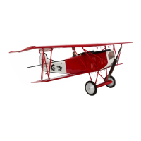
Key specifications including dimensions, weight, and power requirements for the Fokker D.VII.

Assembly Guidance and Requirements

Using the Manual

Guidance on how to understand and follow the assembly manual instructions.

Required Tools and Adhesives

List of tools and adhesives needed for building the model aircraft.

Radio and Power Systems Requirements

Specifications for radio control system and power components for the aircraft.

UltraCote Covering Colors

Available colors for the model's covering material.

Recommended Equipment

Recommended Radio Systems

Recommended radio brands and models for optimal performance.

Recommended Engine Setups

Recommended engine configurations for 2-stroke, 4-stroke, and electric power systems.

Pre-Assembly and Support Information

Before Starting Assembly

Pre-assembly checks and preparation steps for model aircraft parts.

FS One Flight Simulator

Information about the FS One flight simulator software.

WEEE Disposal Guidelines

Guidelines for proper disposal of electronic waste in the EU.

Product Information and Safety

Warranty Information

Details on the product warranty coverage and limitations.

Damage Limits and Liability

Manufacturer's liability limitations regarding product use and damages.

General Safety Precautions

Essential safety guidelines for operating the hobby product.

Customer Support and Repairs

Kit Contents

Contents of Kit

List of all parts included in the aircraft kit.

Items Available Separately

List of additional items that can be purchased separately.

Section 1: Radio Installation

Required Parts and Tools

List of parts, tools, and adhesives for radio installation.

Servo and Receiver Mounting

Procedures for mounting servos and receiver, and connecting extensions.

Section 1: Radio Installation (Continued)

2.4GHz Remote Receiver Mounting

Mounting procedure for a 2.4GHz remote receiver and antenna placement.

Switch Mounting

Cutting opening and mounting the switch to the fuselage side.

Section 2: Aileron Servo Installation

Required Parts and Tools

List of parts, tools, and adhesives for aileron servo installation.

Servo Mounting Block Preparation

Preparing and gluing servo mounting blocks to the hatch.

Section 2: Aileron Servo Installation (Continued)

Servo Placement and Drilling

Marking and drilling screw locations for servo mounting.

Securing the Servo

Mounting the aileron servo to the blocks with screws.

Section 2: Aileron Servo Installation (Continued)

Servo Horn and Extension Connection

Modifying servo horn and connecting servo extension.

Routing Extension Through Wing

Routing the servo extension through the wing and preparing exit point.

Section 2: Aileron Servo Installation (Continued)

Wing Hatch and Pushrod Connection

Securing the servo hatch and connecting pushrods to control horns.

Section 2: Aileron Servo Installation (Continued)

Pushrod Bending and Securing

Bending and connecting pushrods to servo arms.

Repeat for Second Aileron Servo

Repeating the installation process for the other aileron servo.

Section 3: Joining the Wing Panels

Required Parts and Tools

List of parts, tools, and adhesives for wing panel joining.

Spar Preparation and Fitment

Marking and fitting wing spars into the panels.

Section 3: Joining the Wing Panels (Continued)

Epoxy Application for Joining

Applying epoxy to joiner and spar pockets for panel bonding.

Joining Wing Panels

Joining the wing panels and ensuring a tight fit.

Section 3: Joining the Wing Panels (Continued)

Wing Rib Epoxy and Panel Assembly

Applying epoxy to wing ribs and joining panels.

Reinforcing the Wing Joint

Applying a covering strip to reinforce the wing joint.

Section 4: Wing Installation

Required Parts and Tools

List of components and tools for wing installation.

Cabane Strut Installation

Installing forward and rear wing cabane struts to the fuselage.

Section 4: Wing Installation (Continued)

Servo Lead Routing and N-Strut Attachment

Routing servo leads and attaching N-struts to the top wing.

Preparing for Top Wing Attachment

Exposing blind nuts for securing the top wing.

Section 4: Wing Installation (Continued)

Bottom Wing Assembly and Securing

Installing the wing tube, bottom wing panels, and N-struts.

Section 5: Tail Installation

Required Parts and Tools

List of parts, tools, and adhesives for tail installation.

Vertical Fin Attachment to Stabilizer

Fitting, marking, trimming, and gluing the vertical fin to the stabilizer.

Section 5: Tail Installation (Continued)

Stabilizer Alignment and Attachment

Positioning stabilizer, tracing fuselage, trimming, and applying epoxy.

Section 5: Tail Installation (Continued)

Finalizing Stabilizer Attachment

Applying epoxy to fuselage saddle and attaching the stabilizer.

Section 6: Rudder and Elevator Linkage Installation

Required Parts and Tools

List of parts, tools, and adhesives for linkage installation.

Rudder Pushrod Installation

Routing, marking, bending, and connecting the rudder pushrod.

Section 6: Rudder and Elevator Linkage Installation (Continued)

Securing Rudder Pushrod and Elevator Linkage

Securing rudder pushrod and installing elevator pushrod and clevis.

Section 7: Landing Gear Installation

Required Parts and Tools

List of parts and tools for landing gear installation.

Tail Skid and Main Gear Positioning

Fitting the tail skid and positioning the main landing gear legs.

Section 7: Landing Gear Installation (Continued)

Securing Landing Gear Legs and Spreader Wing

Attaching gear legs to fuselage and securing the spreader wing.

Section 7: Landing Gear Installation (Continued)

Axle Preparation for Wheel Mounting

Sliding axle, placing O-rings, and creating a flat spot for wheel collar.

Section 7: Landing Gear Installation (Continued)

Wheel Installation and Securing

Installing wheel backplate, collar, and rebuilding the wheel.

Section 8a: 4-Stroke Engine Installation

Required Parts and Tools

List of components and tools for 4-stroke engine installation.

Firewall Preparation and Mount Installation

Positioning template, drilling, and installing blind nuts and engine mount.

Section 8a: 4-Stroke Engine Installation (Continued)

Engine Positioning and Throttle Pushrod Routing

Verifying throttle arm, marking pushrod hole, and positioning engine.

Section 8a: 4-Stroke Engine Installation (Continued)

Throttle Servo and Connector Installation

Mounting throttle servo and securing pushrod connector.

Section 8a: 4-Stroke Engine Installation (Continued)

Throttle Linkage and Battery Installation

Centering servo, securing pushrod, and mounting receiver battery.

Section 8a: 4-Stroke Engine Installation (Continued)

Fuel Tank, Muffler, and Weight Box Installation

Securing fuel tank, attaching muffler, and mounting weight box.

Section 8b: 2-Stroke Engine Installation

Required Parts and Tools

List of components and tools for 2-stroke engine installation.

Firewall Preparation and Mount Installation

Positioning template, drilling, and installing blind nuts and engine mount.

Section 8b: 2-Stroke Engine Installation (Continued)

Engine Positioning and Throttle Pushrod Routing

Marking pushrod hole, positioning engine, and reinforcing servo holes.

Section 8b: 2-Stroke Engine Installation (Continued)

Throttle Servo and Connector Installation

Mounting throttle servo and securing pushrod connector.

Section 8b: 2-Stroke Engine Installation (Continued)

Throttle Linkage, Battery, and Fuel Tank Installation

Securing pushrod, mounting battery, and installing fuel tank.

Section 8b: 2-Stroke Engine Installation (Continued)

Weight Box and Muffler Installation

Mounting weight box and attaching muffler and fuel lines.

Section 9: Electric Motor Installation

Required Parts and Tools

List of components and tools for electric motor installation.

Firewall Preparation and Motor Mounting

Positioning template, drilling, and mounting motor to firewall.

Section 9: Electric Motor Installation (Continued)

Motor, Weight Box, and Speed Control Mounting

Attaching motor, weight box, and mounting the electronic speed control.

Section 9: Electric Motor Installation (Continued)

Battery Tray and Battery Installation

Attaching battery to tray and securing the tray in the fuselage.

Section 10: Cowling and Cockpit Installation

Required Parts and Tools

List of components and tools for cowling and cockpit installation.

Cowling Preparation and Dummy Engine Attachment

Marking cowl mounting, trimming engine, and attaching exhaust and engine.

Section 10: Cowling and Cockpit Installation (Continued)

Cowl Baffle and Mounting Hole Preparation

Installing baffles and drilling mounting holes in the cowling.

Securing the Cowling to Fuselage

Fastening the cowling to the fuselage with screws.

Section 10: Cowling and Cockpit Installation (Continued)

Cowling Airflow and Adjustment Openings

Cutting openings for air exit and needle valve adjustment.

Section 10: Cowling and Cockpit Installation (Continued)

Propeller and Pilot Installation

Attaching propeller, pilot, and optional cockpit cover hole.

Cockpit Preparation for Machine Guns

Sanding paint on cockpit cover for machine gun attachment.

Section 10: Cowling and Cockpit Installation (Continued)

Machine Gun and Cockpit Cover Attachment

Gluing machine guns and installing the cockpit cover.

Section 11: Control Throws

Aileron and Elevator Control Throws

Recommended throw amounts and expo settings for ailerons and elevators.

Rudder Control Throws

Recommended throw amounts and expo settings for the rudder.

Section 12: Recommended Center of Gravity (CG)

CG Location Marking

Identifying and marking the recommended Center of Gravity point on the wing.

Balancing the Aircraft

Procedures for balancing the model using a stand or fingertips.

Pre-Flight and Engine Adjustment

Pre-Flight Checks

Final checks of radio installation, control surfaces, and engine.

Engine Adjustment Steps

Steps for engine break-in, field adjustment, and ensuring reliable operation.

Radio Testing and General Safety

Range Testing Your Radio

Procedure for checking the radio system's operational range before flying.

Safety, Precautions, and Warnings

Important safety guidelines, precautions, and warnings for operating the model.

Building and Flying Notes

2008 Official AMA National Model Aircraft Safety Code

General Safety Rules

General rules and definitions for model aircraft operation.

Radio Control Safety Rules

Specific safety rules pertaining to radio-controlled model aircraft.

Related product manuals