Page GB-32
Installation and connection
Connecting to the mains
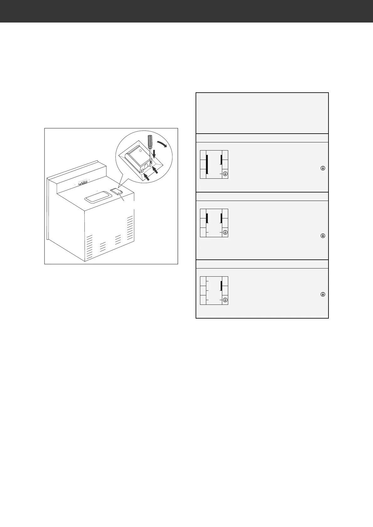
The terminal box and connection diagrams
can be found on the backside of the oven.
Terminal box
1. Before accessing the terminals, switch
off all supply circuits and secure them
against being switched on again.
2. Make sure that all poles of the connection
cables are disconnected and that effec-
tive earthing is possible.
3. Use a screwdriver to open the terminal
box.
4. Connect the wires and, if necessary,
the enclosed brass bridges to the corre-
sponding contact terminals of the cooker
power connection in accordance with the
circuit diagrams shown here.
5. Lay the connection cable behind the
stove so that it does not touch the rear
wall of the cooker. The rear cooker wall
becomes hot while it is in use.
L1–L3: Phase(s)
N: Neutral conductor
PE: Protective conductor (earth wire)
220–240 V ~, 50/60 Hz
L1
N
PE
3
2
1
4
5
L1 to (bridged)
N to
(bridged)
Protective conductor (PE) to
Conductor cross-section:
3 x 10 mm
2
380–415 V 2N~, 50/60 Hz
L2
L1
N
PE
3
2
1
4
5
L1 to
L2 to (bridged)
N to
(bridged)
Protective conductor (PE) to
Conductor cross-section:
4 x 2.5 mm
2
380–415 V 3N~, 50/60 Hz
L2
L3
L1
N
PE
3
2
1
4
5
L1 to , L2 to , L3 to
N to
(bridged)
Protective conductor (PE) to
Conductor cross-section:
5 x 1.5 mm
2