and fixation bolt with an appropriate sealing paste. Remove the excess sealing paste after assembly. Check
carefully if the air gaps between the various components are properly sealed.
After assembly and sealing, a paint system that matches the selected atmospheric corrosion class according to
ISO 12944 will be applied. Refer to the “Order Acknowledgement”.
Protect the oil seals of the gear unit against paint and harmful external influences.
Recommended sealing paste: refer to your supplier. In case of doubt, refer to Hansen Industrial Transmissions nv.
6.3. EXTERNAL LOADS
If external loads act on the gear unit, thrust blocks must be installed against the unit's feet, to prevent the gear
unit from shifting.
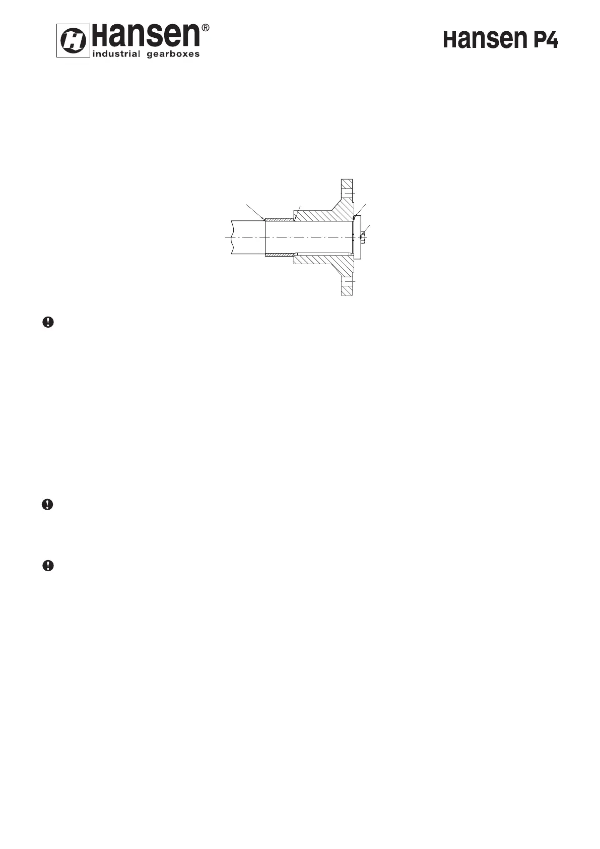
Components transmitting radial load to the shaft should be mounted as close as possible to the housing.
Avoid exaggerated tension in transmission belts mounted on input or output shafts. On gear units with built-on
motor and V-belt drive, tension has been factory set. Tension should be rechecked after 24 hours of operations.
Chain transmissions must be mounted without preliminary tension.
In case a pinion is mounted on the shaft extension of the gear unit, care should be taken to have normal required
backlash between pinion and gear and good contact pattern must be assured.
6.4. ERECTION
6.4.1. Levelling
Always mount gear unit in the position for which it was ordered.
Before altering this mounting position of the gear unit, please consult Hansen Industrial Transmissions nv. It may
be necessary to adapt the lubrication system.
6.4.2. Alignment
Align the gear unit as accurately as possible.
Install the gear unit horizontal, taking into account a max. inclination equal to 5 mm per 1 m (5/32 inch per 3
feet or 5 mrad or 17 arc minutes) or a max. indicated on the outline drawing for positions other than horizontal.
Use three fixation points of the gear unit for alignment. Adjust the other fixation points by shimming to 0,1mm
(0.004 inch).
6.4.2.1. Connection gear unit - machine: allowable misalignment at the low speed shaft (except for
single stage gear units)
The misalignment must be minimized to improve the steadiness of bearing and coupling life span. Ensure that
the alignment remain unchanged at all operating conditions. The unavoidable misalignments may not exceed the
values mentioned in the service manual of the coupling, unless otherwise stated on the certified drawing. These
instructions apply for couplings provided by Hansen Industrial Transmissions NV and listed on the dimensional
drawing.
For couplings NOT delivered by Hansen industrial Transmissions nv (H.I.T.), H.I.T. must be consulted. An
evaluation of external factors which act on the gear unit (maximum admissible misalignment, overhung load on
shaft ends, etc.) allows to check and to guarantee the good functioning of the gear unit.
ENGLISH
18
A
B
C
D
17
 Loading...