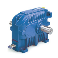
The gear unit can only be lifted with lifting cables or lifting chains fixed to the mounted lifting eye bolts or
integral rods.
The weight of the gear unit (or drive) and other instructions are mentioned on the dimensional drawing.
Always refer to the dimensional drawing before starting handling and transport activities.
The length of lifting cables or lifting chains must be chosen in such way that the angle between lifting cables or
lifting chains is smaller than 45°.
If the gear unit is part of a drive package, the lifting points of the gear unit may not be used to lift the complete
drive package. Refer to the dimensional drawing of the drive package to determine and use the appropriate
lifting points.
Note
Proceed with caution for handling of gear units equipped with external components.
Pay attention that the external components will not be damaged when handling or transporting the gear unit.
6. INSTALLATION
6.1. FITTING OF ACCESSORIES
The metric shaft extensions are equipped with keyways according to DIN 6885 "Blatt 1 - Form N1 or N3".
Threaded centre holes in these shafts are according to DIN 332 Teil 2 Form D.
Couplings should be mounted on the shafts with fit according to specifications. Refer to the certified drawing of
the gear unit and the dimensional drawing of the coupling. In case of doubt please refer to Hansen Industrial
Transmissions nv.
Remove the protection from the shaft extensions and check the key fit and the keyway height in the component to
be mounted onto the shaft. Heating the component to 80-100°C (175-210°F) will be helpful in case of
interference fit. The threaded centre hole in the shaft may be used to assist in mounting the components onto the
shaft.
Never mount components by hammering as this may cause damage to the bearings.
Never use rigid couplings except on free end machine shafts (e.g. mixers, aerators) or in executions
with a torque arm.
6.2. COUPLINGS MOUNTED ON THE SHAFT ENDS OF THE GEAR UNIT – CORROSION PROTECTION
The coupling hubs are mounted on the shaft ends so that the front surfaces are flush or the front surface of the
shaft end remains for a minimum length within the bore of the coupling hub.
If necessary, a spacer between shaft shoulder and coupling hub is mounted.
Where applicable, the coupling hub is secured on the shaft end with thrust washer and fixation bolt.
Refer to the certified drawing.
The assembly of coupling hub, spacer, thrust washer and fixation bolt must be corrosion resistant in accordance
with the application and the atmospheric corrosion class (referring to ISO 12944) determined and mentioned by
the customer.
For the cases where coupling hub, spacer, thrust washer and fixation bolt are supplied and mounted by Hansen
Industrial Transmissions nv, all measures are taken to get a corrosion-resistant assembly in accordance with the
application and the atmospheric corrosion class (ISO 12944) as mentioned in the “Order Acknowledgement”.
If the coupling hub, spacer, thrust washer and fixation bolt are provided and mounted by the customer, he
ensures that the assembly will be corrosion-resistant in accordance with the selected atmospheric corrosion class
according to ISO 12944.
Preservation – sealing paste and painting - recommendation
Degrease and clean all components. Only the bore in the coupling hub may be slightly greased to facilitate
mounting on the shaft end. All other contact surfaces must remain clean and free of grease. Coat all contact
surfaces (A, B, C, and D - see figure at next page) between shaft shoulder, spacer, coupling hub, thrust washer
ENGLISH
17
16

 Loading...