6.6.3. Mounting of the torque arm
After fitting and securing the gear unit to the driven shaft (see par. 6.6.1 or 6.6.2), fix unit by means of the
optionally supplied torque arm to a fixed torque reaction point. Refer to the certified drawing or catalogue for
torque arm location on gear unit.
The connection between torque arm and reaction point must remain flexible and resilient. This is achieved by
preloading the disc springs of the torque arm.
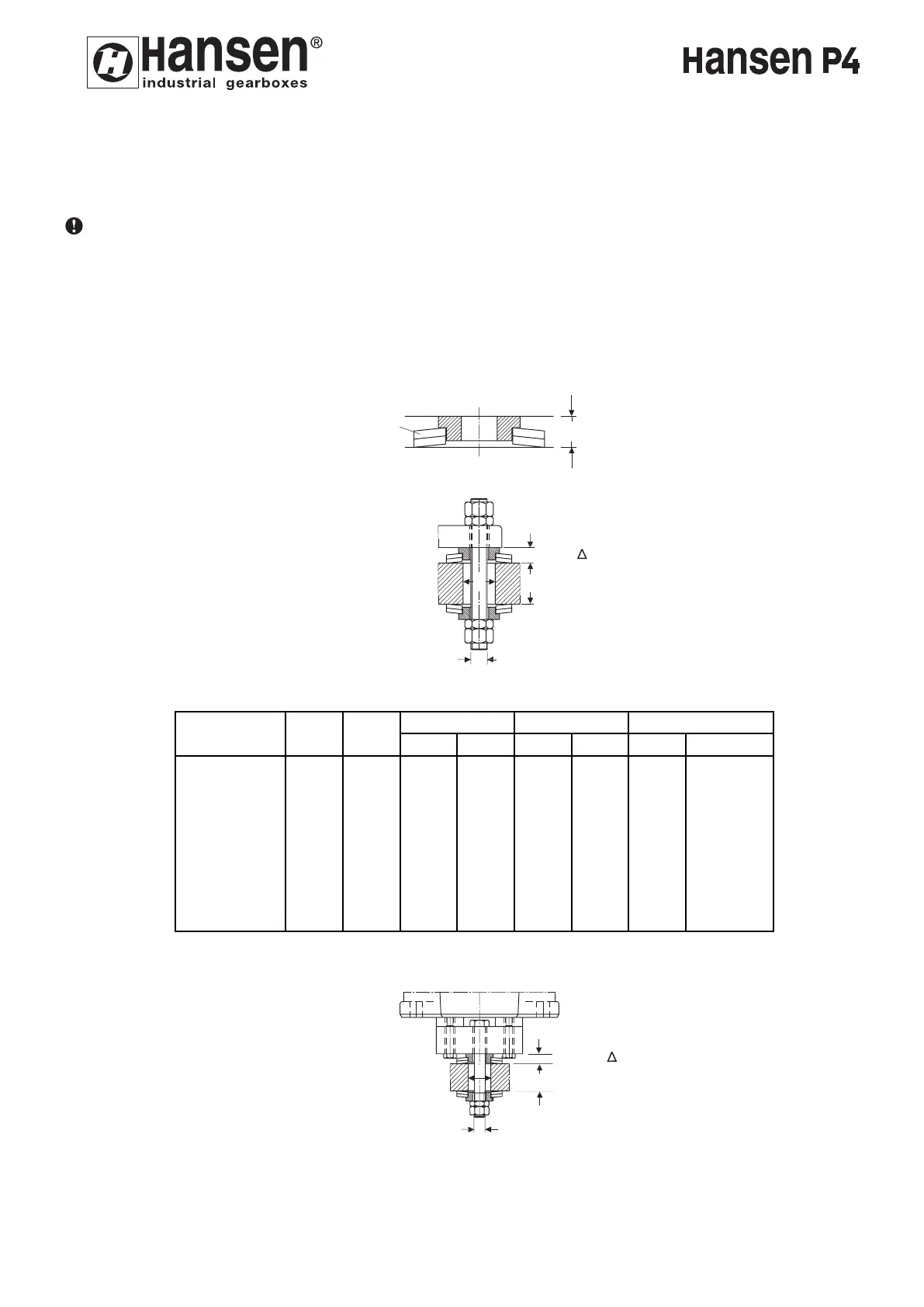
The preload of the disc springs (A) will be adjusted as follows:
- Determine the spacing S (fig. 3a), this is the spacing of the disk springs in unloaded and unmounted condition.
- Screw the inner nut until spacing S1 (spacing between gear unit and fixed point) is reached,
where S1 = S - ΔS (fig. 3b, 3c, 3d).
ΔS = spacing obtained after compression of the disk springs (table 2, 3 and 4) due to the weight of the gear
unit and tightening of the inner nut.
- When the prescribed spacing S1 is obtained, lock the inner nut by tightening outer nut against it.
ENGLISH
25
S
A
FIG.3a
PR
S
1
= S - S
PT
D
FIG.3b
Table 2
Gear unit D PT PR max ΔΔ
ΔΔ
S A
size
QH.A2
±5
35 M16
mm
40
inch
1.57
mm
0,7
inch
0.028
Q*
2 x 2
DIN 2093
A 80
QH.B2
QH.C2
QH.D2
QH.E2
35
45
M20
M24
45
60
M24
M30
50
60
1.97
2.36
60
75
2.36
2.95
0,7
0,9
0.028
0.035
0,9
1,0
0.035
0.039
2 x 2
2 x 2
A 80
A 100
2 x 3
2 x 3
A 100
A 125
QH.F2
QH.G2
QH.H2
60
60
M30
M36
60 M36
75
90
2.95
3.54
90 3.54
1,0
1,0
0.039
0.039
1,0 0.039
Q*: number of disc s
prings
2 x 3
2 x 4
A 125
A 125
2 x 4 A 125
S
1
= S - S
PR
PT
D
FIG.3c
24