9.1.2. Oil-to-air coolers
The service manual of the lubrication and cooling system gives detailed information about the oil-to-air cooler.
9.2. ADDITIONAL WATER COOLING
All water cooling systems must be connected to a non-calcareous water supply. See also the service manual on
lubrication and cooling system and/or technical leaflets on specific instrumentation. The use of seawater must be
specified with the order; coolers suited for use of seawater are available.
When the gear unit is not operating and freezing temperatures may occur, the water must be drained from the
cooling system. Drain facilities have to be provided by the end user.
Unless otherwise stipulated, the water flow indicated on the dimensional drawing is the required rate for water at
20°C (70°F).
Depending on the load, the ambient temperature and the water temperature a lower rate can suffice. Adjust the
water flow to obtain an oil temperature during operation between 60 and 80°C (140 and 180°F).
9.2.1. Oil-to-water coolers
Refer to the certified drawing for the connection of the oil-to-water cooler to the coolant supply system.
The service manual of the lubrication and cooling system gives detailed information about the oil-to-water
coolers.
9.2.2. Cooling coils
The direction of the waterflow is optional.
The cooling coils are suited for fresh as well as for seawater.
Maximum allowable water pressure : 0,8 MPa (8 bar, 116 psi).
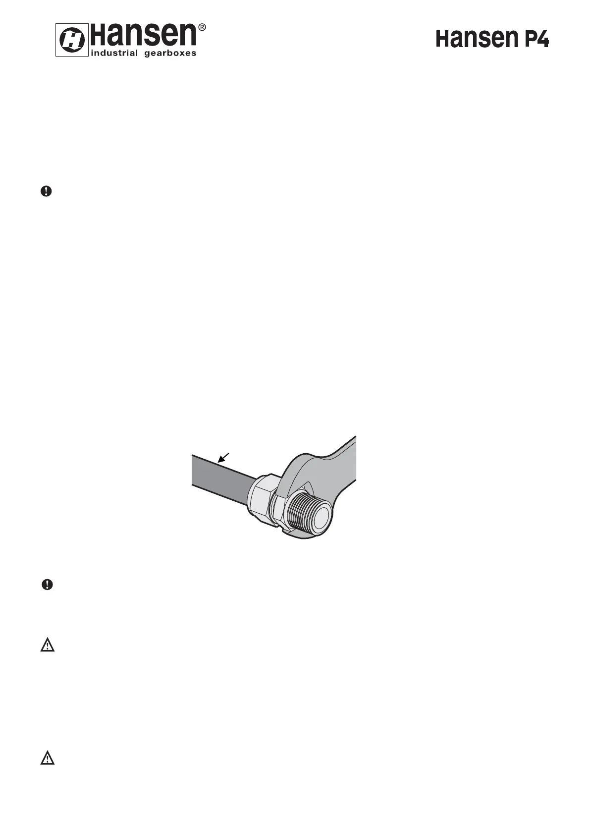
Connection of the cooling coil to the water supply.
Warning: In order to avoid torsioning of the cooling coil, hold the premounted connection with a suitable
wrench as shown in fig. 6.
10. BACKSTOPS
Backstops are subject to wear and must be inspected or replaced at intervals depending on operating conditions.
The customer must take all necessary precautions to prevent that failure of the backstop could cause physical
injury and/or severe damage to the drive and/or application.
The time span between two checks of functioning depends on the operating conditions and the activation
frequency, but should never exceed two years. These inspections are preferably carried out by qualified personnel
authorized by Hansen Industrial Transmissions nv.
In case the backstop is part of a hoist drive which is subject to a periodical safety inspection, the check of the backstop
must be included in the inspection procedure.
In case of transport of people: the user has to follow the local legislation re. the inspection of safety devices.
ENGLISH
31
FIG. 6
cooling coil
30