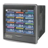
To prevent chattering during the use of Contact Input Counter, setup the
coefficient speed at 1 or 30 cps in Function Setup Mode.
Input Logic Setup Status can be
verified in Function Setup Mode.
Internal Impedance is 4.7 , and
switches over to Pull Up or Pull
Down from NPN/PNP Selection.
(Refer to Input Connection)
Timer Mode Setup Method
Indicated Time Range
Output Connection
Timer Operation Mode
Timer[TIM]Output Operation
Function Setup Mode (Timer / Twin timer)
Initial value
Setup Item
Scale
Time
range
Operation
Mode
Output
time
BATCH
Output
Input
time
Input
logic
Key
Lock
Memory
for power
failure
Device
Change
Contents
Timer
Twin Timer
10 (Decimal) / 60 (Sexagesimal)system
* No display for Total and TWIN TIMER
mode
Minimum input time selection 1
/20 (INHIBIT), (START), RESET
Current time and Batch count
Convertible by dip switch It is not available
to change setup in power input menu.
value are saved when power failure
Remove a data when power failure
Key Lock
, , , No use keys
No use keys
No use for all keys ( key exception)
Set Batch output port
:Relay : Transistor)
0.01sec ~ 999999(9999)h
UP/DOWN selectable
Twin timer is not available with
1 Stage output model.
Refer to output operation mode char
1 Stage setup type
In TIM(TIMER) setup
In TTIM(TWIN TIMER) setup
* One short or
self-maintenance for OUT2(OUT)
NPN Input
PNP Input
Key lock setup in operation
condition (4stages)
In Total(Display only)product
2 Stage setup type
4 digits Time Range
6 digits Time Range
Range Selection
Decimal
System
99.99 s
999.9 s
9999 s
9999 m
9999 h
Sexagecimal
System
59.99 s
9 m 59.9 s
59 m 59 s
99 h 59 m
99 d 23 h
Decimal
System
9999.99 s
99999.9 s
999999 s
999999 m
999999 h
Sexagecimal
System
59 m 59.99 s
9 h 59 m 59.9 s
99 h 59 m 59 s
9999 h 59 m
9999 d 23 h
UP
DOWN
s : second m : minute. h : hour d: day
Example of Contact Output
Avoid the flow of excessive current since it
is 250 V a.c NO 3 A (loadresistance) NC 2 A
(load resistance), and theconnection must
correspond to standard connection method.
Example of Non-Contact Output
Connect surge observer (diode,varistor)
on the both ends of the load when using
inductive load (relay etc.),and must use
with GND since the internal circuit and
non-contact output are isolated from one
another.
Calculate power load and load to prevent
the non-contact output from exceeding the
maximum of 30 V 100
CP1/INHIBIT function stops the time.
[S.---] is activated when CP2 (START) is ‘ON’
[S ---] is activated when CP2 is maintained ‘ON’, and resets when ‘OFF’.
[P ---] activates with ‘POWER ON’
Setup as in order to compensate for interruption of electric
power during ‘POWER OFF’ (Indicates the Memorized Value when electric
power is inputted again.)
TIM(TIMER)Setup TTIM(TWIN TIMER)Setup For TOTAL Model
Power RUN / ON delay
Signal START / ON delay
Signal START / ON delay
Signal RUN / ON delay
Signal RUN / OFF delay
Interval / Signal RUN
Interval / Signal START
Flicker / Signal START
Flicker (Counter Mode)
Flicker (Counter Mode)
Flicker (Counter Mode)
Signal Addition
Power RUN
ON delay
Power RUN
OFF delay
Signal START
ON delay
Signal START
OFF delay
Power ON RUN
OFF time
Power RUN
Signal RUN
1 Stage Setup Type Output is OUT.
INHIBIT (CP1) temporarily stops the time.
Runs when ‘POWER ON’
When Reset signal is authorized, process value initializes and runs.
Total(Indicator) type of product does not have setup mode for output time and Batch
One stage output mode does not have twin timer function
Power RUN / ON delay

 Loading...