Do you have a question about the Harbor Breeze AFTONSHIRE and is the answer not in the manual?
Read and understand the entire manual before assembly, installation, or operation.
Critical safety notices regarding installation risks, injury, and electrical hazards.
Turn off circuit breakers and wall switch before installation to prevent electrical shock.
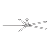
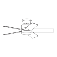
Select between downrod mount (standard/angled ceiling) or closemount (standard ceiling).
Ensure blades are 30 inches from obstructions and 7 feet from the floor.
Loosen and remove canopy mounting screws, then remove mounting bracket from canopy.
Attach mounting bracket to outlet box using provided hardware, ensuring it supports the fan's weight.
Remove pin and clip from downrod; loosen set screws in motor housing yoke.
Insert downrod through yoke cover and canopy, threading wires through the downrod.
Align downrod holes with yoke, re-install pin and clip, tighten set screws and nut.
Measure and cut lead wires to 8 inches above the hanging ball if desired.
Strip 3/4 inch insulation from wires and twist strands for connection.
Align hanging ball slot with bracket tab and install fan onto mounting bracket.
Remove the canopy cover from the canopy, noting it may require tapping.
Remove alternate screws/lock washers from the top of the motor housing.
Pull wires through canopy hole and attach canopy to motor housing with screws.
Hang the fan on the mounting bracket tab using a non-slotted canopy hole.
Safety notices regarding wire connectors, grounding, wire colors, and dimmer switches.
Connect wires using wire connectors, screwing them clockwise for remote control operation.
Connect ground wires to ceiling ground, and receiver power wires to ceiling power.
Wrap electrical tape around wire connectors and ensure no bare wire is visible.
Slide receiver into mounting bracket, push wires into outlet box, let antenna hang.
Lift canopy to bracket, align holes, twist to lock, and secure with canopy screws.
Align blade holes with motor housing, insert blade screws, and tighten securely.
Loosen motor plate screws, align fitter plate, allow molex connections through, and tighten screws.
Loosen fitter plate screws, remove one, and remove plastic holding motor housing wires.
Connect LED light kit wires to motor housing wires (White to White, Black to Blue/Black).
Arrange wiring in fitter plate, align LED light kit with screws, twist to lock, and tighten.
Align shade slots with fitter plate protrusions and turn clockwise until secure.
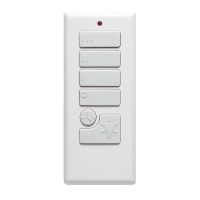
Install remote control bracket screws into desired location and place transmitter inside.
Locate batteries and transmitter, remove protective covering, and install two AAA batteries.
Important warnings about battery polarity, choking hazards, mixing, recharging, and disposal.
Press and hold LEARN button within 30 seconds of powering on to synchronize remote with fan.
Explains buttons for fan speed (High, Medium, Low, Off), light control, and color modes.
Use the reverse switch on the motor housing for seasonal airflow optimization.
Left position for downward airflow (cooling), Right position for upward airflow (heating assist).
The reverse switch must be fully left or right; middle position prevents fan operation.
Solutions for fan not starting, including checking reverse switch, power, and wiring.
Addresses causes like loose blades, cracked blades, or improper speed controls.
Troubleshooting steps for wobbling, including checking blade tightness and mounting security.
Solutions for light malfunction, focusing on canopy wiring and LED kit connections.
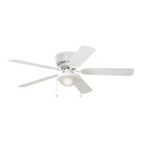
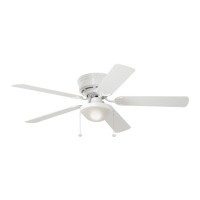
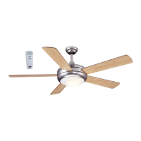
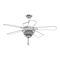
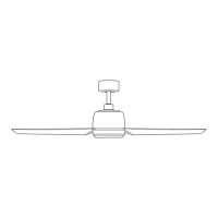
This document describes the Aftonshire Ceiling Fan, Model #SOH52MBK3LR, an electrical appliance designed for air circulation and lighting in residential settings. It includes instructions for assembly, installation, operation, and maintenance, along with safety information and warranty details.
The Aftonshire Ceiling Fan provides air movement and illumination. It can be mounted in two styles: downrod mount (standard or angled ceiling) or closemount (standard ceiling only). The fan features a reversible motor for seasonal performance optimization, allowing for downward airflow in warmer weather to create a wind chill effect, and upward airflow in cooler weather to help move stagnant, hot air off the ceiling area. The integrated LED light kit provides illumination and is dimmable to 10%. The fan and light functions are controlled via a remote control transmitter.
| Brand | Harbor Breeze |
|---|---|
| Model | AFTONSHIRE |
| Category | Fan |
| Language | English |