7
H
White
Black
Blue
I
12 13
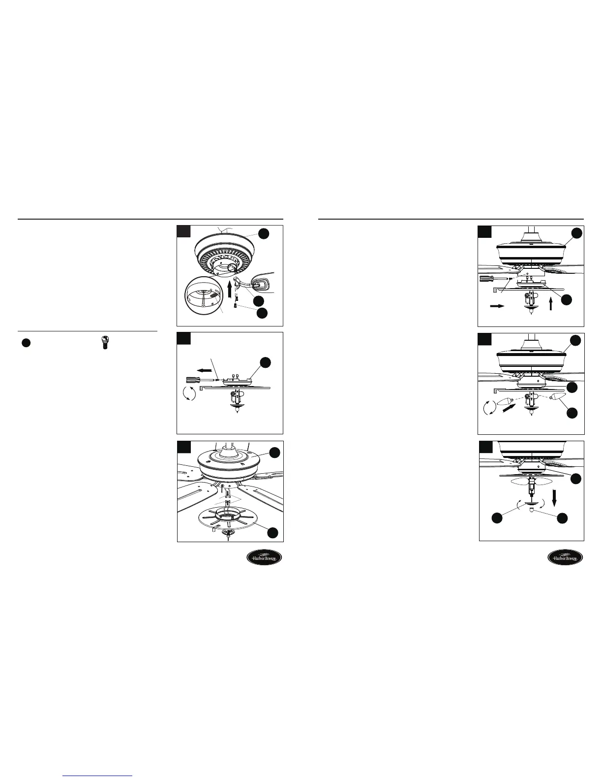
FINAL INSTALLATION
5. Align the post of blade bracket (F) to the slot on
the bottom of the motor housing (H). Secure blade
bracket (F) using blade bracket screws (EE).
NOTE: The switch cup has an access hole that
is sealed with a waterproof rubber plug. Remove
the rubber plug to allow the screwdriver to reach
the screws in the blade bracket. Position the blade
bracket on the motor and tighten by inserting the
screwdriver through the access hole. Once all blade
brackets have been attached, replace the rubber
plug in the access hole.
Repeat this step for the remaining blade assemblies.
8. Attach light kit (I) to the bottom of the motor
housing (H) by aligning the holes in each part and
re-installing the previously removed screws (Step
6, page 12). Tighten securely.
9. Install bulbs (K) into sockets in light kit (I).
Note: This fan has an energy-saving wattage limiter
included. If candelabra-base bulbs are more than
190 watts, light will automatically turn off. Please
ensure bulb wattage is always less than 190 watts.
10.Removethepreassemblednial(M)andbowlcap
(L) from the light kit (I).
FINAL INSTALLATION
6
Screw
I
10
I
M
L
9
H
K
I
8
I
Screw
H
7. Connect the adapter plug of the BLUE wire from the
fan motor assembly (H) to the adapter plug of the
BLACK wire from the light kit (I) and connect the
adapter plug of the WHITE wire from the fan motor
assembly (H) to the adapter plug of the WHITE wire
from the light kit (I).
6. To install the fan WITH the light, remove and
save the three preassembled screw from the
switch of light kit (I).
NOTE: To install this fan WITH the light kit, continue
to step 6. To install the fan WITHOUT the light kit,
proceed to step 13.
EE
Blade Bracket Screw x 16
Hardware Used
 Loading...