26
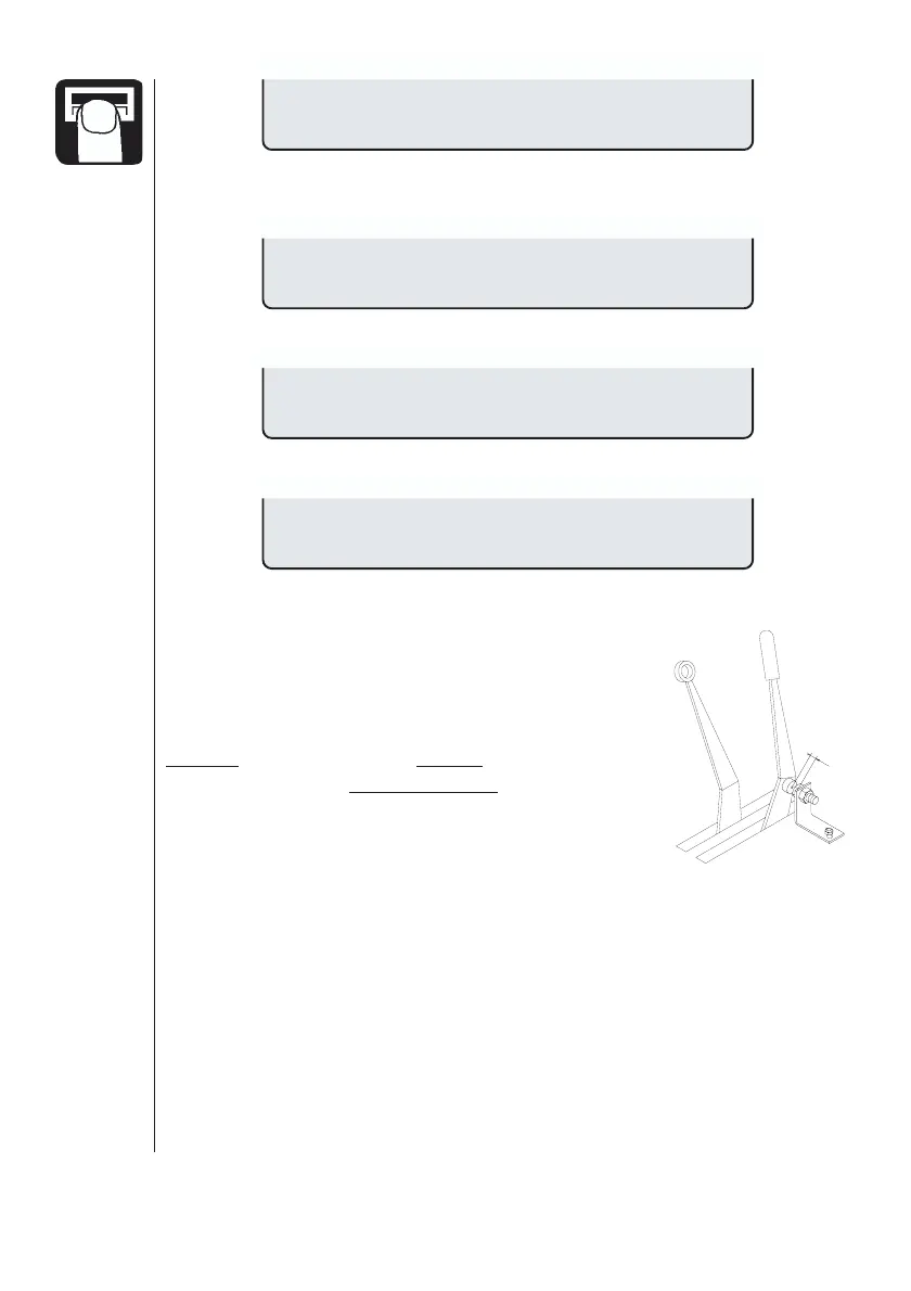
With the south side of the magnet facing the transducer
at a distance of 5 to 7 mm. This indicates correct function.
To test the revolutions sensor
Every magnet will give a count, indicating correct function.
To test the optional transducer.
Area meter
For HM 1500 with manual control unit, the area
meter will register area continuously when the
sprayer is disconnected. When the south side of the
magnet is located directly in front of the transducer,
the area meter will stop registering area.
When using a HM 1500 with manual control unit
and switch box, or HC 2500 with EC control box, all
the switches must be turned on.
If you do not want to utilise the area meter transducer, the main on/off
switch can be used to start and stop the area register.
Mistblowers and HM 1500/HC 2500
Points to note if the system is used on a mistblower.
• Work width is the same as the spray width of the mistblower.
• Not active switches on the control box are set to zero work width.
• Use the Tank method to calibrate the flow transducer.
• Blower fan revolutions can be read in the revolutions readout.
Magnet To Sens. On
Revolutions test
Turn slowly xxx
Optional sensor
T165-0006
5-7 mm
 Loading...