28
Note the relation is inverse:
• To raise the displayed volume, the PPU is lowered.
• To lower the displayed volume, the PPU is raised.
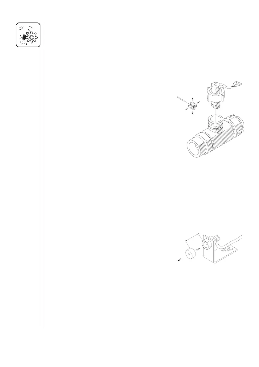
Testing flow transducer (Ref. no. 728816)
Wire connections: BROWN wire to positive of 12 volt battery.
BLACK wire to negative.
BLUE wire to multimeter positive.
1. Check the rotor turns freely.
2. Each vane in the rotor has a magnet in it
with the pole facing out.
Check that the 4 magnets are present.
3. Check every second magnet has the
same pole orientation so the rotor
magnets are N - S - N - S.
4. Connect negative from multimeter to
negative of battery.
5. Set multimeter to DC volt.
6. By turning the mill wheel slowly, this will register approx. 8.0 +/- 1 volt
with the diode on and 0.3 +/- 0.1 volt with the diode off with every
second magnet.
Testing speed transducer (Ref. no. 729058)
Wire connections: BROWN wire to positive of 12 volt battery.
BLACK wire to negative.
BLUE wire to multimeter.
1. Connect negative from multimeter to
negative of battery.
2. Set multimeter to DC volt.
3. By bringing the south pole of a magnet
(distance 5 mm +/- 2 mm) by the trans
ducer, this will register 0.3 +/- 0.1 volt.
4. By removing the magnet, this will register 7 .0 +/- 1.0 volt.
T165-0004
N
S
5-7 mm
1
/
8
-
1
/
4
N
S
S
N
T045-0003
 Loading...