7
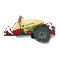
HARDI NAVIGATOR
Fig 7
1 Measure the correct wheel track (Centre of right hand
tyre to centre of left hand tyre). Extend or retract each
side equally to achieve the desired alteration.
2 Attach sprayer to the tractor and engage tractor
parking brake.
3 Place stop wedges in front of and behind the right
hand wheel. Using suitable heavy duty equipment,
jack up the left hand wheel. Ensure secure support
for the sprayer body.
4 To release axle wedge for the left hand wheel axle
and extend or retract the axle:
Turn Nut C (Fig 8) anti-clockwise to allow approx.
30mm clearance. With an open-ended spanner,
turn Nut D (Fig 8) against anchor plate until hold on
axle is released. Shift axle to measured position.
Tyres
Equal pressure in both tyres is essential. Pressure
should be kept as low as practical, i.e. baggy when the
tank is full. For recommended pressures see Page 22.
NOTE! Sprayers fitted with controllers must always
maintain the same tyre pressure as when calibrated.
WARNING! Never inflate tyres above the specified
pressures. Over inflated tyres can explode and
cause severe personal injuries.
Connecting hydraulics
Please refer to the Boom Operator’s Manual supplied
with your sprayer documentation regarding connecting
hydraulics, boom operation, adjustment and maintenance.
5
To tighten axle wedge and secure axle at required width:
Turn Nut D anti-clockwise to allow movement of
stop wedge.Turn Nut C clockwise against anchor
plate to draw stop wedge up against the axle and
hold it in position. Tighten to torque of 280 Nm,
then lock by re-tightening Nut D.
6 If the wheels are reversed and exchanged, remem-
ber to tighten the wheel nuts to the specified torque -
rim plate to hub 490 Nm.
7 Repeat the procedure on the right hand wheel.
8 Check the distance from the centre of the tyre to the
centre of the tank, to ensure the distance is equal
from left to right.
9 Re-tighten the clamp bolts and wheel nuts to the
specified torque after 8 hours of work.
IMPORTANT! Always place a jack under axle and lift
the wheel to remove the load from the clamps before
tightening the clamp bolts.
Fig 8

 Loading...