8
HARDI NAVIGATOR
Control boxes and power supply
Power requirement is 12V DC. Note Polarity!
For EVC: Brown pos. (+), Blue neg. (-).
The control boxes for EVC-operating unit and D.A.H.
are fitted in the tractor cabin at a convenient place.
Tapping screws can be used for mounting.
Connecting electric controls
Control boxes must be fitted in the tractor cabin at a
convenient place. 12 V power sockets are required.
The wires must have a cross-sectional area of at least
4.0 mm
2
to ensure sufficient power supply. The boxes
must be fused according to the following table.
Control Box Polarity / Wire colour Fuse (Amp)
(+) (-)
EC operating unit Brown Blue 8
Foam marker White Black 16
Distribution valves Brown Blue 8
NOTE! Please refer to the Boom Operator’s Manual
supplied with your sprayer documentation regarding
connecting hydraulics,boom operation, adjustment and
maintenance.
Controls Setup Procedure
Before spraying, the EVC operating unit is adjusted
using clean water (ie without chemicals).
1 Choose the correct nozzle for the spray job. Make
sure that all nozzles are the same type and capacity.
Please see your dealer or the Hardi Spray Technique
book for Nozzle selection guidance.
2 Switch on the EVC using the Controller.
3 Activate all distribution valves to the open position.
4 Decrease the pressure until the pressure control
valve handle (A Fig 9) stops rotating (min. pressure).
5 Put the tractor in neutral and adjust the PTO revolu-
tions to the intended travelling speed. ThePTO must
be kept between 300- 600 rpm (540 pump) or 650-
1100 rpm (1000 pump).
6 Increase the pressure until the required pressure is
shown on the pressure gauge.
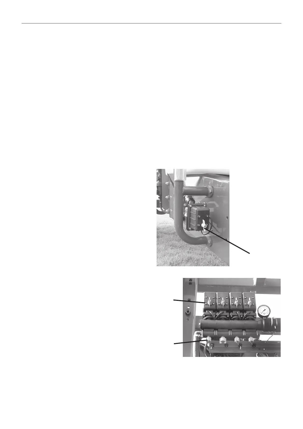
Pressure equalisation Setup Procedure
1
Close the first section of the distribution valves (A Fig 10).
2 Turn the first section adjusting screw (B Fig 10) until
the pressure gauge shows the same pressure again.
3 Leaving the 1st section off, repeat procedure to adjust
with the next section off. Continue until all sections are
off - the gauge should still read the same pressure.
Subsequent Adjustments
NOTE! Hereafter adjustment of pressure equalisation
will only be needed when you change to nozzles with
other capacities or the nozzleoutput increases as the
nozzles wear.
Please see your dealer or the Hardi Spray Technique
book for Nozzle selection guidance.
Emergency operation
Boom
Refer to the
Troubleshooting
section in the
FALCON or
EAGLE PARALIFT Boom Operator’s Manual
supplied
with your sprayer documentation. In case of power
failure on units fitted with solenoid valves, the boom can
be operated manually by pressing the the centre of
individual buttons on the solenoid valves. This is done
by locking the by-pass valve.
EVC Operating Unit
Refer to the
Troubleshooting
section on Page 21.
In case of power failure, the problem may be due to a
blown fuse. Refer to the Controller Manual supplied with
your sprayer.
It is possible to operate all functions of the operating unit
manually. First disconnect the Controller, then manually
turn the emergency control knobs.
Fig 10
Fig 9
A
A
B

 Loading...