3 - Description
3.5
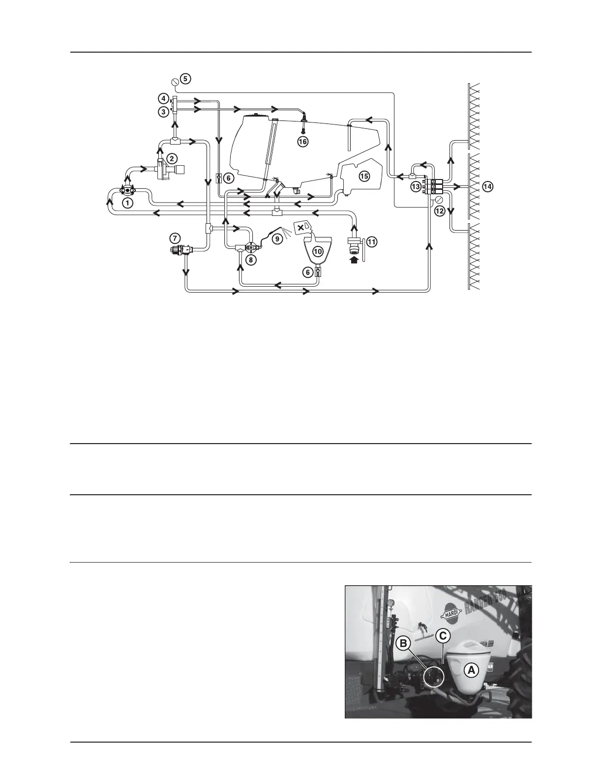
Diagram - Centrifugal Liquid system
Control unit
EVC - Electrical Valve Control. The ON/OFF is linked to the section valves, which results in a very quick response to ON/OFF.
The operating unit is constructed of modules and is electrically controlled via a remote control box.
Filters
In-line pressure filters are fitted at each boom section.
All filters should always be in use and their function checked regularly. Pay attention to the correct combination of filter
mesh size. The mesh size should always be less than the flow average of the nozzles in use.
HARDI® FILLER
The HARDI® FILLER (A) is situated on the sprayer’s left side, just behind
the valve system. The valve (B) engages the HARDI® FILLER, used when
mixing the chemicals. The rinsing wand (C) is used for rinsing the
hopper or chemical container .
See section “Operation” for operating instructions.
1. Suction valve
2. Pump
3. Tank rinse valve (optional)
4. Agitation valve
5. Remote system pressure gauge
6. Check valve
7. Pressure regulator
8. HARDI® FILLER valve (optional)
9. HARDI® FILLER rinse (optional)
10. HARDI® FILLER (optional)
11. Quick Fill (optional)
12. System pressure gauge
13. Boom section valves
14. Boom
15. Flush tank (optional)
16. Tank rinse nozzle (optional)
 Loading...