4 - Sprayer setup
4.6
Electrical connections
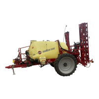
Power supply
Power requirement is 12V DC. Note polarity! The wires must be at least
10 awg. (4.0 mm²) to ensure a sufficient power supply. For the operating
unit, the tractor circuit should have an 8 Amp fuse. The supplied power
connector is standard on most newer tractors. If using a tractor with a
different power connector, it is necessary to disassemble connector and
attach the wires to the actual tractor connector.
Control boxes
Control boxes are fitted in the tractor cabin at a convenient place.
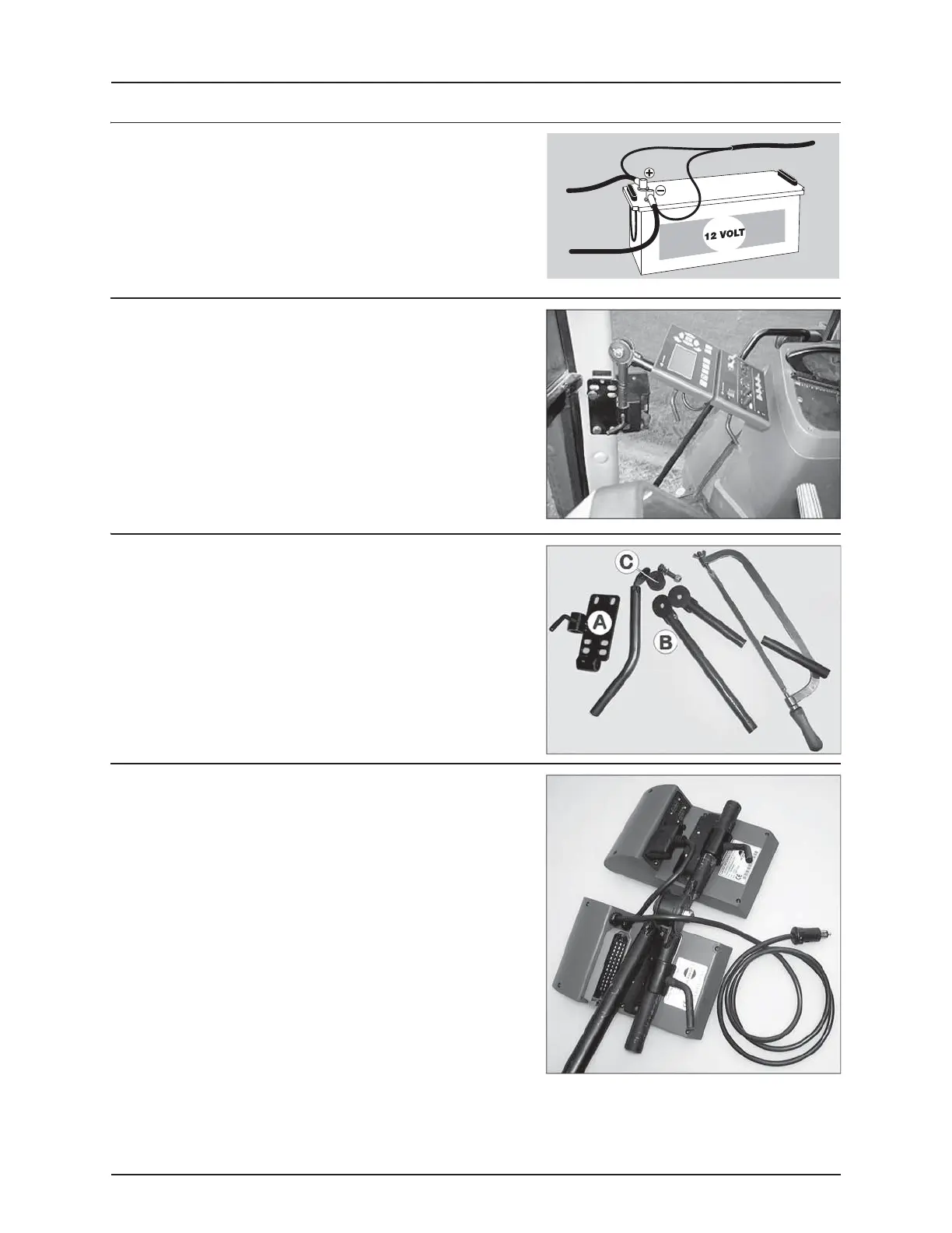
Installation of control unit brackets
The supplied tractor pillar bracket (A) has a hole spacing of 3.9 in.
(100mm) and 4.7 in. (120mm). Check tractor instructions manual for
information regarding attachment points.
Three tubes (B) are supplied. One, two or all three may be used. They can
be bent and shortened. A spacer (C) is also supplied to allow further
attachment possibilities. Find the best solution for your tractor or
vehicle.
Tube (B) plate is staggered, so if correctly orientated, all boxes will line
up.
Installation of control box - EVC control unit
Find a suitable place in the tractor’s cabin. Best recommended
placement is to the right of the driver seat and in combination with the
Hydraulics control unit. It should be secured from movement.
ATTENTION! Tractor driver’s seat is the intended working place
during operation.
 Loading...