2005 PDI: All Models 1-5
CAUTION
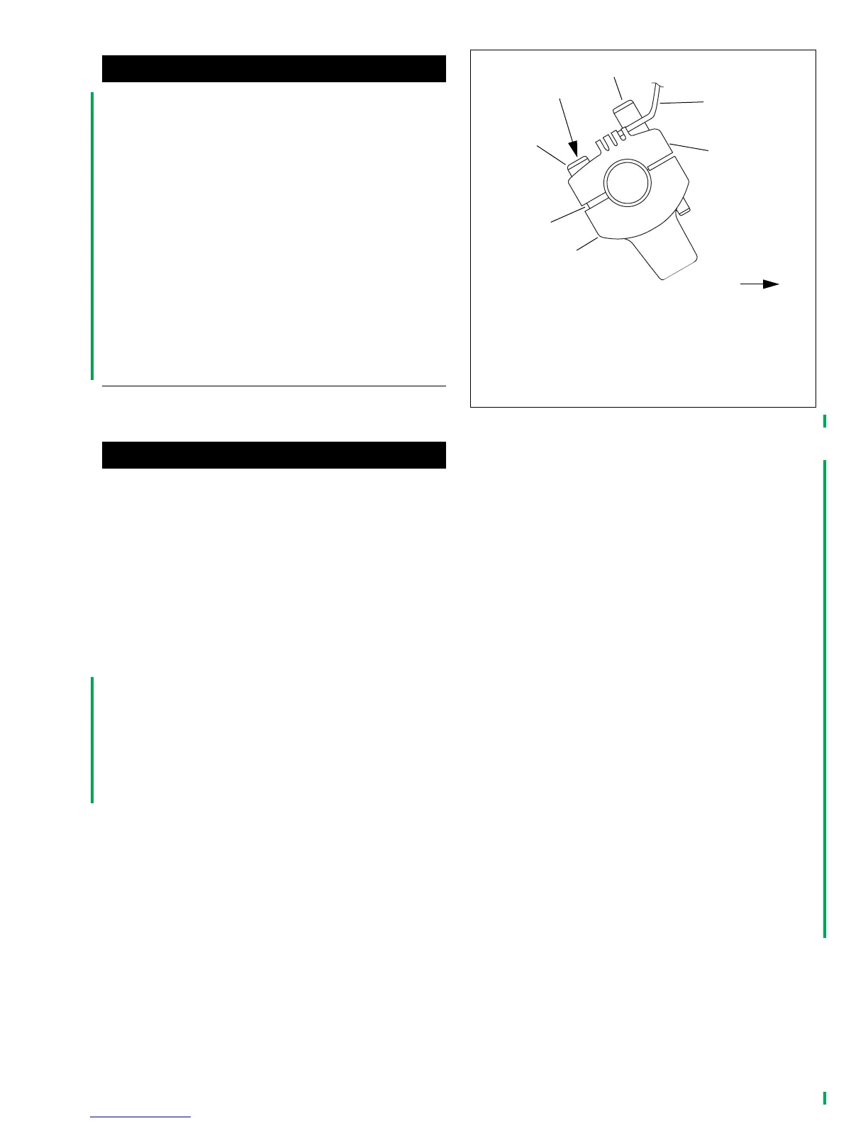
See Figure 1-9. Attach brake line as shown before remov-
ing motorcycle from pallet. If brake line is not secured, it
could be pinched and damaged in front fork stop.
8. Attach brake line to bottom of steering stem with clamp
(4) and screw (5). Tighten to 96-120
in-lbs
(10.9-13.6
Nm).
9. See Figure 1-8. Remove shipping clamps (3) from the
handlebar. Remove protective block (4) on throttle. Dis-
card shipping clamps and protective block.
10. Install clutch cable in clip on left downtube.
11. Install the plastic wire retainers on the handlebar switch
conduits and push into the holes in the handlebars.
Replace any broken wire retainers.
ADJUSTING HANDLEBARS–
ALL MODELS
General
CAUTION
Never adjust handlebars using excessive force. Doing so
may result in damage to handlebar or clamp.
NOTE
If handlebars are positioned for a rider of normal size, post-
pone adjustment until customer has checked their position. If
customer requests changing handlebar position, perform the
adjustment before delivering the motorcycle to the customer.
Always center the handlebar laterally (sideways) in the han-
dlebar clamps.
Before removing motorcycle from pallet, adjust handlebars
according to the following procedures:
Dyna Glide, Softail, XL 883, XL 883L and
XL 1200R Models
1. See Figure 1-10. Loosen four screws (3 and 4) of han-
dlebar upper clamp (6).
2. To be sure handlebars are properly centered, verify that
equal amounts of knurled areas on handlebar protrude
from outboard sides of upper handlebar clamp.
NOTE
On some models, knurled areas of handlebar will be com-
pletely hidden by upper handlebar clamp and will not be visi-
ble at all when handlebar is centered properly.
3. Raise handlebars to normal riding position and hold in
position.
4. Models with cast-in spacers (2) in upper clamp:
a. Tighten two rear screws (3) until cast-in spacers
contact handlebar lower clamps (1).
b. Dyna and Sportster models: tighten front screws (4)
to 12-18 ft-lbs (16.3-24.4 Nm). Softail models:
tighten front screws (4) to 12-15 ft-lbs (16.3-20.3
Nm).
c. Dyna and Sportster models: final tighten rear
screws to 12-18 ft-lbs (16.3-24.4 Nm). Softail mod-
els: final tighten rear screws to 12-15 ft-lbs (16.3-
20.3 Nm). Slight gap between upper and lower
clamps should exist at front.
5. Models without cast-in spacers in upper clamps:
a. Tighten all four screws finger-tight, maintaining
equal gaps between upper and lower clamps front to
back.
b. Dyna and Sportster models: tighten rear screws to
12-18 ft-lbs (16.3-24.4 Nm). Softail models: tighten
rear screws to 12-15 ft-lbs (16.3-20.3 Nm).
c. Dyna and Sportster models: tighten front screws to
12-18 ft-lbs (16.3-24.4 Nm). Softail models: tighten
front screws to 12-15 ft-lbs (16.3-20.3 Nm).
Figure 1-10. XL 883, XL 883L, XL 1200R,
Dyna Glide and Some Softail Models
pd0031d
1. Lower clamp (2)
2. Cast-in spacers (2)
3. Rear screw (2)
4. Front screw (2)
5. Instrument bracket (if equipped)
6. Upper clamp
3
2
4
1
5
6
Tighten
first
FRONT
 Loading...