1-6 2005 PDI: All Models
XL 883C and XL 1200C Models
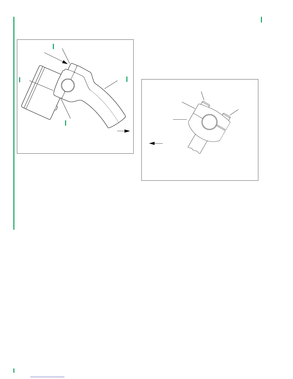
1. See Figure 1-11. Loosen four screws (1, 2) of handlebar
upper clamp (3).
).
2. To be sure handlebars are properly centered, verify that
equal amounts of knurled areas on handlebar protrude
from outboard sides of upper handlebar clamp.
NOTE
On some models, knurled areas of handlebar will be com-
pletely hidden by upper handlebar clamp and will not be visi-
ble at all when handlebar is centered properly.
3. Raise handlebars to normal riding position; hold in posi-
tion. Tighten two front screws (1) to 12-18 ft-lbs (16.3-
24.4 Nm).
4. Tighten rear screws (2) to 12-18 ft-lbs (16.3-24.4 Nm).
FLHT, FLHTC, FLHTCU and FLHTP
1. Remove ignition switch knob and inner fairing cap
according to appropriate Touring Models Service Manual
instructions.
2. See Figure 1-12. Loosen two rear screws (3) of handle-
bar upper clamps (2).
3. If there is a gap between either handlebar lower clamp
(1) and upper clamp at front, tighten front screw (4) only
enough to close gap. If handlebars do not move up and
down freely, loosen rear screws until they do.
4. Raise handlebars to normal riding position. To be sure
handlebars are properly centered, verify that equal
amounts of knurled areas on handlebar protrude from
outboard sides of both handlebar clamps.
5. Tighten rear screws to 12-16 ft-lbs (16.3-21.7 Nm). Slight
gap should exist between upper and lower clamps at
rear.
6. Check torque on front handlebar clamp screws. Tighten
screws to 12-16 ft-lbs (16.3-21.7 Nm).
7. Reinstall inner fairing cap and ignition switch knob
according to appropriate Touring Models Service Manual
instructions.
Figure 1-11. XL 1200C, XL 883C Custom Models
1. Front screw (2)
2. Rear screw (2)
3. Upper clamp
4. Lower clamp
pd0031f
2
1
4
3
FRONT
Tighten
first
Figure 1-12. FLHT/C/U and FLHTP Models
1. Lower clamp (2)
2. Upper clamp (2)
3. Rear screw (2)
4. Front screw (2)
FRONT
pd0021a
3
2
1
4
 Loading...