2005 PDI: All Models 1-7
FLHR/C/S/I Road King, FLHP, FLHPE
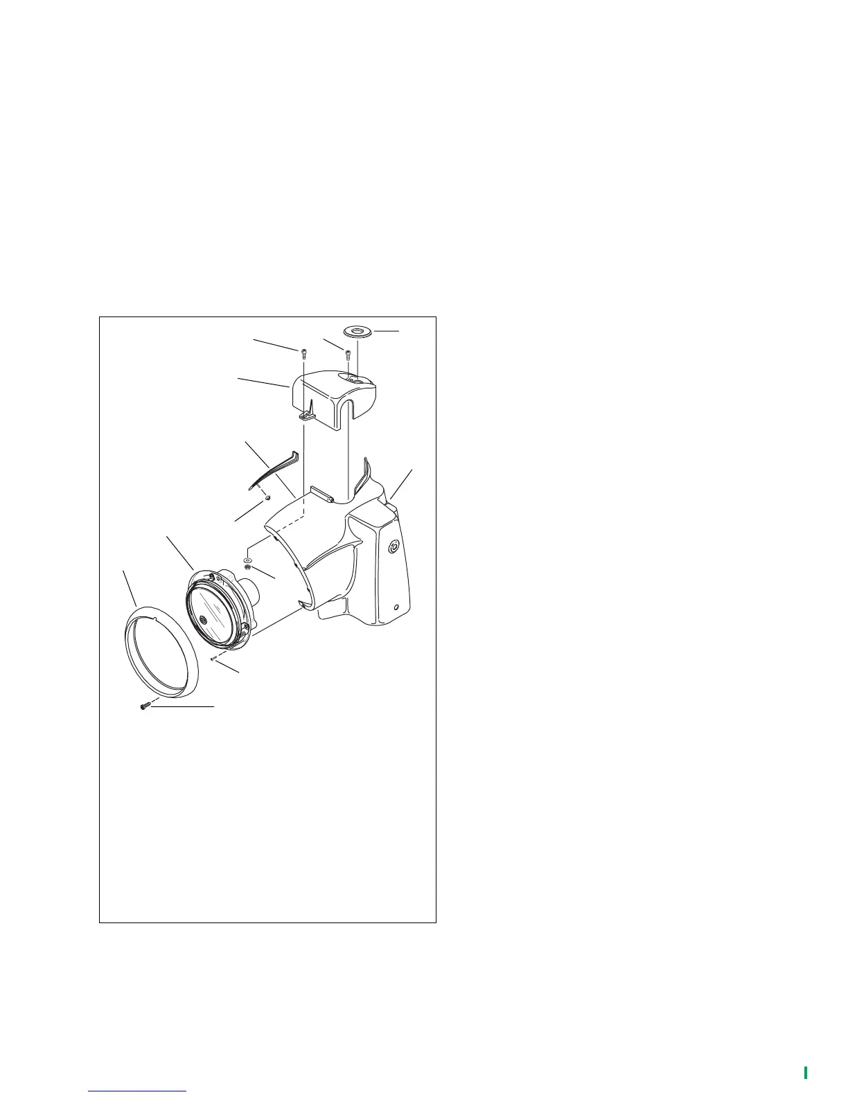
1. See Figure 1-13. Remove screw (12) securing chrome
ring (11) to headlamp nacelle (7). Remove chrome ring.
2. Remove eight screws (10) securing headlamp assembly
(9). Squeeze two external tabs (if present) to remove
wire connector at back of headlamp bulb. Remove head-
lamp assembly from vehicle.
3. Remove nut (1) (inside nacelle) securing nacelle trim (2).
4. On Police models, disconnect tachometer lead.
5. Remove nacelle trim. Loosen (but do not remove) front
handlebar clamp shroud screw (3), nut and washer (4).
6. Gently pry off fork lock plate (5) at rear of handlebar
clamp shroud (8). Remove two screws (6) beneath lock
plate.
7. Loosen four acorn nuts securing nacelle halves to fork
studs. Spread nacelle halves slightly and remove handle-
bar clamp shroud.
8. Adjust handlebars following steps 2.-6. of the FLHT,
FLHTC, FLHTCU and FLHTP procedure given on previ-
ous page.
9. Reinstall handlebar clamp shroud. Tighten acorn nuts
securing nacelle halves to fork studs to 72-108
in-lbs
(8.1-12.2 Nm).
10. Install two screws (6) to handlebar clamp shroud and
tighten to 10-20
in-lbs
(1.1-2.3 Nm). Gently press fork
lock plate (5) into place on handlebar clamp shroud.
11. Tighten front handlebar clamp shroud nut (4) to 10-20
in-
lbs
(1.1-2.3 Nm).
12. On police models, connect tachometer lead.
13. Install nacelle trim (2). Install nut (1) (inside nacelle) secur-
ing nacelle trim. Tighten to 15-20
in-lbs
(1.7-2.3 Nm).
14. Connect wire connector to socket on back of headlamp
bulb. Install and secure headlamp assembly to nacelle
with eight fasteners.
15. Secure chrome ring (11) to headlamp nacelle with screw
(12).
NOTE
Check clearance between windshield and clutch cable and
handlebar position prior to completing assembly of vehicle.
Figure 1-13. FLHR/C, FLHP, FLHPE Models
5
pd0226
3
2
1
4
7
1. Nut
2. Nacelle trim
3. Front handlebar clamp shroud screw
4. Nut and washer
5. Fork lock plate
6. Screw (2)
7. Nacelle
8. Handlebar clamp shroud
9. Headlamp assembly
10. Screw (8)
11. Chrome headlamp ring
12. Screw
9
10
12
11
6
8
 Loading...