3.16TOP END OVERHAUL: ASSEMBLY
GENERAL
NOTE
• It is assumed that each step performed on one cylinder is
automatically repeated on the other.
• Do not mix 2007 and later pistons with earlier style pistons.
New style pistons have tapered wrist pin boss. The wrist
pin portion of the connecting rod is also tapered.
This section provides a sequential process for engine reas-
sembly after a complete 3.15 TOP END OVERHAUL: DISAS-
SEMBLY. If you reached this section after an inspection or
repair procedure, start where necessary and continue to the
end of the section.
• Piston installation-see 3.16 TOP END OVERHAUL:
ASSEMBLY, Piston.
• Cylinder installation-see 3.16 TOP END OVERHAUL:
ASSEMBLY, Cylinder.
• Cylinder head installation-see 3.16 TOP END OVERHAUL:
ASSEMBLY, Cylinder Head.
• Push rods, lifters and covers installation-see 3.16 TOP
END OVERHAUL: ASSEMBLY, Push Rods, Lifters and
Covers.
• Rocker arm support plate installation-see 3.15 TOP END
OVERHAUL: DISASSEMBLY, Rocker Arm Support Plate.
• Breather assembly installation-see 3.16 TOP END
OVERHAUL: ASSEMBLY, Breather Assembly.
PISTON
TOOL NAMEPART NUMBER
PISTON PIN CIRCLIP
REMOVER/INSTALLER
HD-42317-A
1. Slide approximately 6.0 in. (152 mm) of plastic tubing,
rubber hose or conduit over each cylinder stud, if removed.
Use material with I.D. of 0.5 in. (12.7 mm) to protect cyl-
inder studs and piston from damage.
2. Apply clean H-D 20W50 engine oil to piston pin, piston
bosses and upper connecting rod bushing.
3. Remove water pipe insulation from connecting rod shank.
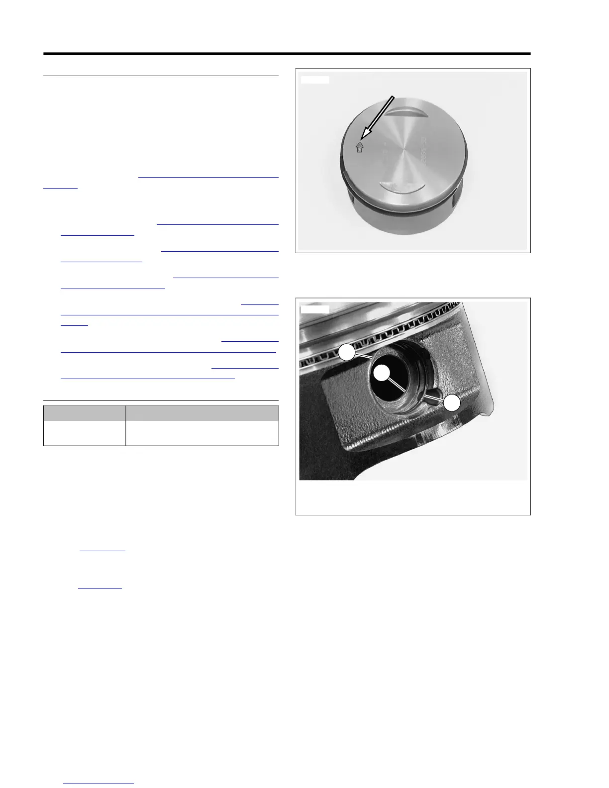
4. See Figure 3-30. Place piston over rod end so that the
arrow stamped at the top of the piston points toward the
front of the engine.
5. See Figure 3-31. Insert piston pin (1) through pin bore and
upper connecting rod bushing. Push pin until it contacts
circlip installed in opposite pin boss. Verify that end gap
(3) for circlip is 180 degrees from opening (2).
6. Place clean shop towels over the cylinder and lifter bores
to prevent the piston pin circlip from falling into the crank-
case.Verify that the circlip groove is clean and free of dirt
and grime.



 To Next Page