7. Install cam support plate over guides.
8. Remove guides and base.
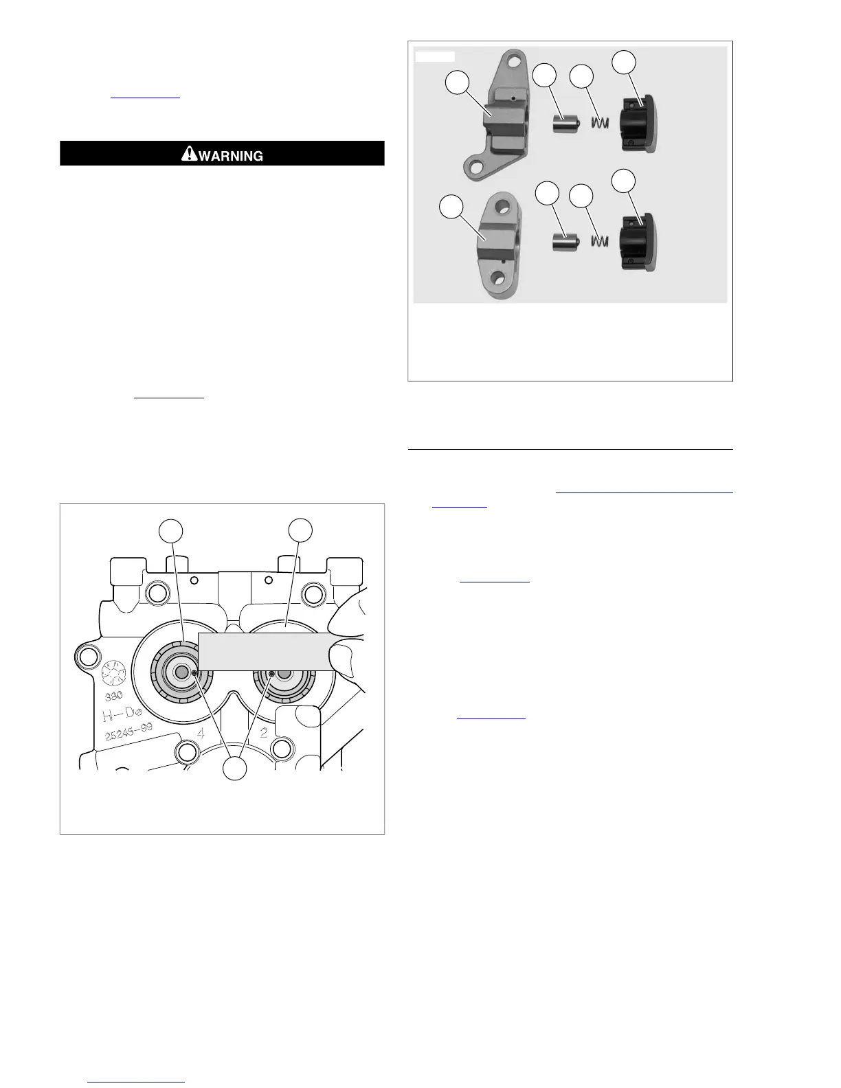
9. See Figure 3-117. Using a straightedge, verify that the
timing marks are in alignment. If they are not, then the
camshafts must be removed, realigned and reinstalled.
Wear safety glasses or goggles when removing or
installing retaining rings. Retaining rings can slip from the
pliers and could be propelled with enough force to cause
serious eye injury. (00312a)
10. Install 0.100 in. (2.54 mm) thick front camshaft spacer
over end of front camshaft.
11. With the sharp edge out, install new retaining ring in
groove at end of front camshaft.
12. Inspect primary and secondary cam chain tensioners.
a. Inspect tensioners for wear. Replace tensioners if
damaged or if chain contact portion of shoe material
is less than 0.060 in. (1.52 mm) thick.
b. See Figure 3-118. Be sure primary and secondary
cam chain tensioners are assembled as shown. If
assembled incorrectly, tensioners will not function
properly.
13. Install secondary cam chain tensioner. Tighten fasteners
to 100-120 in-lbs (11.3-13.6 Nm).
1. Secondary cam chain tensioner
2. Primary cam chain tensioner
3. Piston
4. Spring
5. Shoe
Figure 3-118. Cam Chain Tensioner Assemblies
OIL PRESSURE RELIEF VALVE
Removal
1. Before removal, see 3.26 OIL PUMP, Cleaning and
Inspection.
2. Secure the cam support plate in a vise with access to the
roll pin. Be sure to install a pair of brass jaw inserts in the
vise to avoid damage to the casting.
3. See Figure 3-119. Using a 1/8 in. punch with a small
hammer, carefully tap roll pin (1) from pin hole in cam
support plate. Discard roll pin.
4. Remove spring (2) and valve body (3) from bypass port.
Installation
1. Secure the cam support plate in a vise. Be sure to install
a pair of brass jaw inserts to avoid damage to the casting.
2. See Figure 3-119. Lubricate valve body (3) with clean H-
D 20W50 engine oil. Slide valve body into bypass port of
cam support plate with the open side facing outward.
3. Slide spring (2) into bypass port until seated in open side
of valve body.
4. Start new roll pin (1) into hole in cam support plate.
Compress spring in port using the blade of a small
screwdriver.
5. Holding spring compressed, tap roll pin into cam support
plate until it approaches pin hole on opposite side.
6. Remove screwdriver to release spring. Verify that spring
is straight and square in bore.
7. Using a 1/8 in. punch with a small hammer, carefully tap
roll pin until flush with casting.
3-84 2008 Dyna Service: Engine



 To Next Page