8.10TAIL LAMP
GENERAL
Dyna Glide models are equipped with a tail lamp that uses a
mini harness and circuit board to simplify replacement.
The FXDWG and FXDF use a similar type assembly, but the
lens and base are oriented 180 degrees different from the other
models and there is no chrome taillamp bezel. The FXDWG
and FXDF also use a different mini-harness than the other
models.
TAIL LAMP BULB REPLACEMENT:
STANDARD STYLE
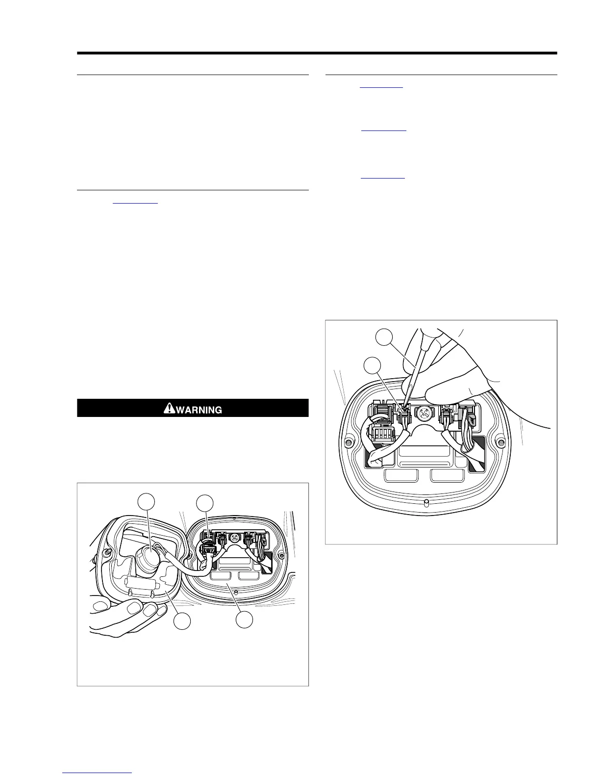
1. See Figure 8-23. Make certain ignition switch is turned
off.
2. Remove two screws and lens from base.
NOTE
For ease of bulb removal, the 4-Pin multilock connector can
be removed from circuit board.
3. Remove (pull) bulb assembly from lens. Remove bulb from
socket.
4. Coat base of new bulb with ELECTRICAL CONTACT
GREASE (Part No. 99861-90). Install new bulb in socket.
5. Install (push) bulb assembly to lens.
6. If removed connect 4-Pin multilock connector to circuit
board.
7. Install lens to base with two screws. Tighten screws to
20-24 in-lbs (2.3-2.7 Nm).
Be sure that all lights and switches operate properly before
operating motorcycle. Low visibility of rider can result in
death or serious injury. (00316a)
8. Turn ignition on and test for proper tail lamp operation.
1. Lens
2. Base
3. 4-Pin multilock connector
4. Bulb assembly
Figure 8-23.Tail Lamp: FXD, FXDC, FXDL
BASE REPLACEMENT
1. See Figure 8-23. Remove two screws and lens from base.
2. Depress locking tab and remove 4-Pin multilock connector
from pin housing.
3. See Figure 8-24. Using a terminal pick or small screw-
driver, depress locking tabs and remove two 2-Pin turn
signal connectors and 6-Pin Power In connector from pin
housing.
4. See Figure 8-25. Remove screw, pin housing and circuit
board from base.
NOTE
The circuit board is a press fit in the tail lamp housing of
FXDWG and FXDF models and requires no screw to hold it in
place.
5. Remove two nuts, screws and base from rear fender.
6. Install new base to rear fender with two screws and nuts.
Tighten screws to 40-48 in-lbs (4.5-5.4 Nm).
7. Install circuit board/pin housing to base with screw. Circuit
board snaps in on bottom.



 To Next Page