2. Remove the screw with lockwasher to release the turn
signal switch bracket. Remove the bracket and switch
assembly from the housing.
3. Continue with TURN-RIGHT SIGNAL SWITCH or FRONT
STOPLIGHT SWITCH procedures which follow.
Turn-Right Signal Switch
1. Perform steps in LOWER HOUSING REPAIR.
2. Cut wire 1.5 in. (38.1 mm) from old switch. Discard old
switch assembly.
NOTE
Replacement turn-right signal switch wires are cut to length of
1.5 in. (38.1 mm) and partially stripped.
3. See 8.28 HANDLEBAR SWITCH ASSEMBLIES for
information on splicing and general repair practices.
4. Continue with 8.29 RIGHT HANDLEBAR SWITCH,
Assembly.
Front Stoplight Switch
1. Perform steps in LOWER HOUSING REPAIR.
2. Carefully remove the wedge between the switch and switch
housing, if present.To remove the switch from the housing,
depress the plunger and slowly rotate switch upward while
rocking slightly.
3. Cut wires 1.0 in. (25.4 mm) from old switch. Discard old
switch.
NOTE
Replacement stoplight switch wires are cut to length of 2.5
in. (63.5 mm) and partially stripped.
4. See 8.28 HANDLEBAR SWITCH ASSEMBLIES for
information on splicing and general repair practices.
5. Carefully depress plunger against inside wall of switch
housing. With thumb over plunger bore, move switch into
the installed position in the switch housing cavity. When
plunger is positioned against thumb, slowly rotate switch
downward while rocking slightly. Release the plunger only
after switch is properly positioned in the cavity.
6. Verify that the plunger is square in the bore and that the
boot is not compressed, collapsed or torn. If necessary,
gently work the plunger in and out until boot is fully
extended.
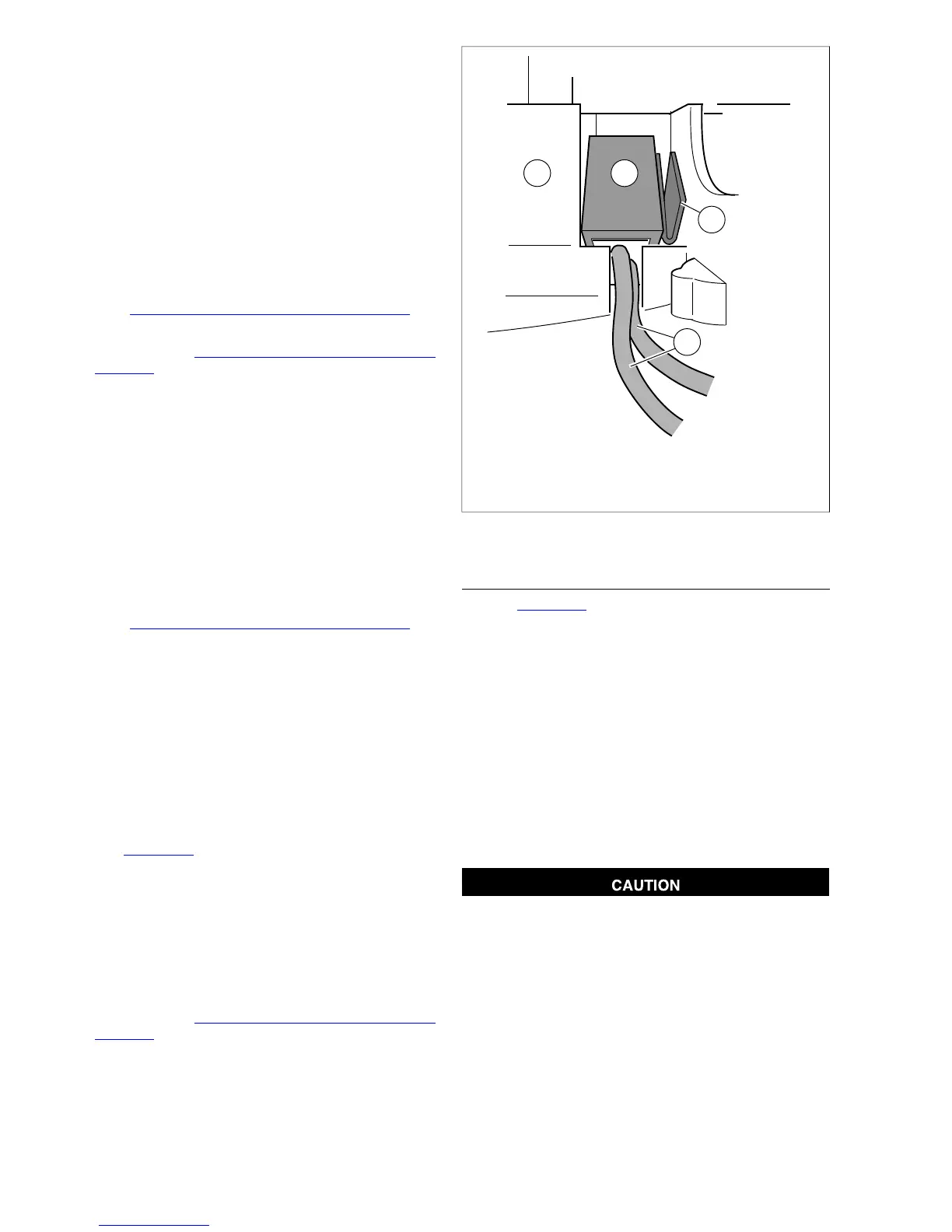
7. See Figure 8-88. Push down on switch (1) so that it bot-
toms against housing and wires (3) run in groove at base
of cavity. With the concave side facing outward, insert
wedge (2) between switch and outboard side of switch
housing.
8. Push wedge down until it also bottoms against housing.
Verify that the plunger is still square in the bore and then
place a drop of RTV Silicone Sealant on upper corner of
wedge.
9. Continue with 8.29 RIGHT HANDLEBAR SWITCH,
Assembly.
1. Stoplight switch
2. Wedge
3. Switch wires
4. Lower switch housing
Figure 8-88. Install Stoplight Switch
ASSEMBLY
1. See Figure 8-89. Insert tapered end of new 7.0 in. (177.8
mm) cable strap (1) into round hole in turn signal switch
bracket (2) and then feed back through using the adjacent
hole. Reserve the oblong hole for the bracket screw.
NOTE
Be sure that all splices are positioned above the turn signal
switch bracket.
2. Place the turn signal switch assembly into the housing,
aligning the oblong hole in the bracket with the threaded
hole in the boss. Be sure that the bracket is fully seated.
Tabs on each side of bracket are captured in slots cast
into switch housing.
3. Start screw with lockwasher to secure bracket inside
housing.
If routed incorrectly, wires can be pinched by casting or
handlebar resulting in switch failure. (00542b)
4. Loop switch wires so that spliced lengths are positioned
across bracket.
5. Capturing conduit about 0.25 in. (6.4 mm) from end,
securely tighten cable strap to draw conduit to bracket.
Remove any excess cable strap material.
6. Install second 7.0 in. (177.8 mm) cable strap capturing
conduit and wire splices. Securely tighten cable strap to
draw splices to conduit. Remove any excess cable strap
material.
8-58 2008 Dyna Service: Electrical
 Loading...