Do not re-use sprocket mounting screws. Re-using
sprocket mounting screws can result in torque loss and
damage to the sprocket and/or belt assembly. (00480b)
Cast Wheel
1. See Figure 2-5. If necessary, install brake disc (8). Verify
that brake disc is clean.
2. On left side of wheel, install five new screws (3) and
washers (4) to attach brake disc (8). Tighten fasteners to
16-24 ft-lbs (21.7-32.5 Nm).
3. FXDF: Install second disc on right side of wheel. Tighten
fasteners to 16-24 ft-lbs (21.7-32.5 Nm).
4. Install spacers (2, 9) with largest chamfered end facing
away from wheel.
5. Verify that wheel and tire are true. See 2.10 CHECKING
CAST WHEEL RUNOUT.
Laced Wheel
1. If hub and rim were disassembled, see 2.7 WHEEL
LACING: 19 INCH RIM or 2.8 WHEEL LACING: 21 INCH
RIM.
2. See Figure 2-7. If necessary, install brake disc (8). Verify
that brake disc is clean.
3. On left side of wheel, install five new screws (3) and
washers (4) to attach brake disc (8). Tighten fasteners to
16-24 ft-lbs (21.7-32.5 Nm).
4. Install spacers (2, 9) with largest chamfered end facing
away from wheel.
5. Verify that wheel and tire are true. See 2.9 TRUING
LACED WHEELS.
INSTALLATION
1. Apply a light coat of LOCTITE ANTI-SEIZE LUBRICANT
to the axle, bearing bores, and the bore of the inner sleeve.
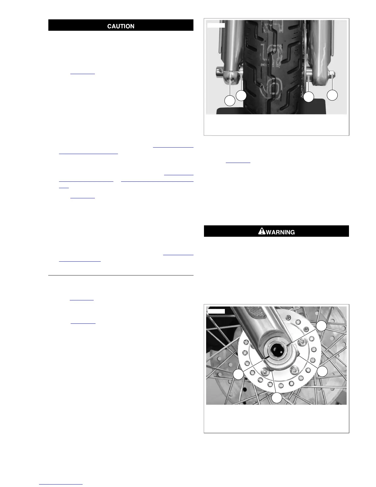
2. See Figure 2-8. Place wheel into front fork and install axle.
Verify that axle spacers (1) on right and left side are
properly installed.
3. See Figure 2-9. Install slider cap with cast-in spacer (1)
toward the rear of the vehicle. Do not tighten fasteners at
this time.
4. Install the washer, lockwasher, and axle nut.Tighten axle
nut to 60-65 ft-lbs (81.3-88.1 Nm). Hold axle stationary
with a steel rod or screwdriver inserted through hole on
right end of axle while tightening.
5. Tighten rear axle cap fastener (2) to 10-14 ft-lbs (13.6-
19.0 Nm), then tighten front axle cap fastener (3) to 10-14
ft-lbs (13.6-19.0 Nm).
1. Spacer (2)
2. Axle nut, lockwasher and washer
3. Slider cap fasteners
Figure 2-8. Front Axle Assembly
6. See Figure 2-3. Install the brake caliper to the fork legs.
a. Loosely install long mounting bolt (1) (metric) into top
hole on fork leg.
b. Install short mounting bolt (2) (metric) into bottom hole
on fork leg. Tighten bottom mounting bolt to 28-38 ft-
lbs (38.0-51.5 Nm).
c. Final tighten the top mounting bolt to 28-38 ft-
lbs (38.0-51.5 Nm).
Whenever a wheel is installed and before moving the
motorcycle, pump brakes to build brake system pressure.
Insufficient pressure can adversely affect brake perform-
ance, which could result in death or serious injury.
(00284a)
7. Pump brake hand lever to move pistons out until they
contact both brake pads. Verify piston location against
pads.