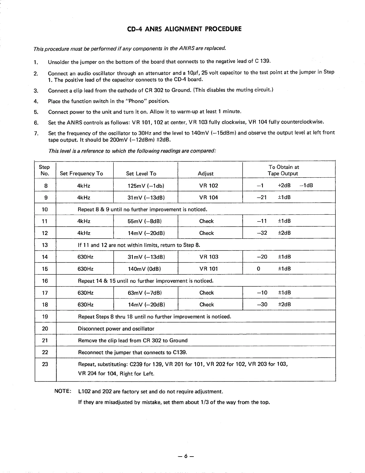
CD-4 ANRS ALIGNMENT
PROCEDURE
This procedure must be
performed
if
any
components in the
ANRS
are replaced.
1.
Unsolder
the
jumper on
the
bottom
of
the board
that
connects
to
the negative lead of C 139.
2.
Connect an audio oscillator through an attenuator and a 1 Oµf, 25 volt capacitor
to
the
test point
at
the jumper
in
Step
1.
The positive lead
of
the
capacitor connects
to
the
CD-4
board.
3. Connect a clip lead from
the
cathode
of
CR
302
to
Ground. (This disables the muting circuit.)
4. Place the function switch
in
the
"Phono"
position.
5. Connect power
to
the
unit and turn it on. Allow it
to
warm-up
at
least 1 minute.
6.
Set
the
AN
RS
controls as follows: V R 101, 102
at
center, V R 103 fully clockwise,
VR
104 fully counterclockwise.
7.
Set
the
frequency
of
the oscillator
to
30Hz and
the
level
to
140mV
(-15dBm)
and observe the
output
level
at left front
tape
output.
It should be 200mV
(-12dBm)
±2dB.
This level
is
a reference
to
which the
following
readings are compared:
Step
To Obtain
at
No.
Set Frequency
To
Set
Level
To Adjust
Tape
Output
8
4kHz 125mV
(-1db)
VR
102
-1
+2dB
-1dB
9
4kHz 31mV
(-13dB)
VR
104
-21
±1dB
10
Repeat 8 & 9 until no further improvement
is
noticed.
11
4kHz
55mV
(-8dB)
Check
-11
±1dB
12
4kHz 14mV
(-20dB)
Check
-32
±2dB
13
If
11
and 12 are
not
within limits, return
to
Step 8.
14 630Hz
31mV
(-13dB)
VR
103
-20
±1dB
15 630Hz
140mV (0dB)
VR
101
0
±1dB
16
Repeat 14 & 15 until
no
further improvement
is
noticed.
17
630Hz
63mV
(-7dB)
Check
-10
±1dB
18
630Hz
14mV
(-20dB)
Check
-30
±2dB
19
Repeat Steps 8
thru
18 until no further improvement
is
noticed.
20 Disconnect power and oscillator
21
Remove
the
clip lead from
CR
302
to
Ground
22 Reconnect
the
jumper
that
connects
to
C139.
23
Repeat, substituting: C239 for 139,
VR
201
for 101,
VR
202
for 102,
VR
203 for 103,
VR
204 for 104, Right for Left.
NOTE: L102 and
202
are factory set and do
not
require adjustment.
If
they are misadjusted by mistake, set them about
1/3
of
the
way from the top.
-6-
 Loading...