f
g
h
e
d
c
b
a
Z
Y
X
W
U
T
S
Q
O
N
M
L
0
1
2
3
4
5
6
7
8
9A
B
C
DE F
G
H
I
J
K
The Bridge
P
R
V
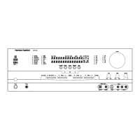
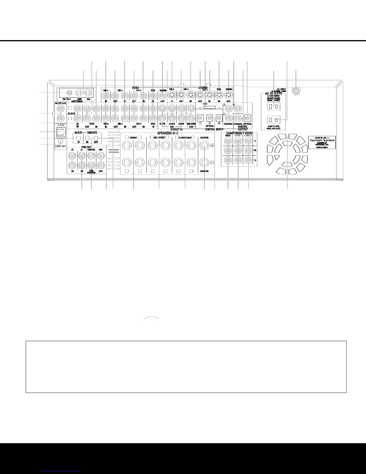
¡ FM Antenna Jack
™ Multiroom Audio Outputs
£ CD Audio Inputs
¢ A-BUS
®
Connector
∞ Multiroom IR Input
§ Remote IR Carrier Output
¶ Preamp Outputs
• Subwoofer Output
ª Remote IR Input
‚ Remote IR Output
⁄ Front Speaker Outputs
¤ Surround Back/Multiroom Speaker Outputs
‹ Surround Speaker Outputs
› Center Speaker Outputs
fi Optical Digital Audio Inputs
fl Component Video Monitor Outputs
‡ Component Video 1 Inputs
° Component Video 2 Inputs
· Fan Vents
a AC Power Cord
b Switched AC Accessory Outlet
c Unswitched AC Accessory Outlet
d Optical Digital Audio Output
e Coaxial Digital Audio Output
f Coaxial Digital Audio Inputs
g S-Video Monitor Output
h DVD S-Video Input
i Video 1 S-Video Input
j DMP Connector
k Video 1 S-Video Output
U Video 2 S-Video Input
V Video 2 S-Video Output
W Video 3 S-Video Input
X 6/8-Channel Direct Inputs
Y Video Monitor Output
Z DVD Audio/Video Inputs
a Video 1 Audio/Video Inputs
b Video 1 Audio/Video Outputs
c Video 2 Audio/Video Inputs
d Video 2 Audio/Video Outputs
e Video 3
Audio/Video Inputs
f Tape Inputs
g Tape Outputs
h AM Antenna Terminals
NOTE: T
o assist in making the correct connections
for multichannel input, output and speaker connec-
tions, all connection jacks and terminals are color-
coded in conformance with the CEA standards
as follows:
Front Left: White
F
ront Right:
Red
Center:
Green
Surround Left: Blue
Surround Right: Gray
Surround Back Left: Brown
Surround Back Right:
T
an
Subwoofer: Purple
Coaxial Digital Audio: Orange
Composite
Video:
Y
ellow
Component Video “Y”: Green
Component Video “Pr”: Red
Component Video “Pb”: Blue
¡ FM Antenna Jack: Connect the supplied indoor
(or an optional external) FM antenna to this ter
minal.
™ Multiroom
Audio Outputs:
Connect these jacks
to the optional external audio power amplifier that is
used for multizone distribution.
£ CD Audio Inputs: Connect these jacks to the
analog audio outputs of a compact disc player or
CD changer
.
¢ A-BUS
®
Connector: Connect this jack to an
optional A-BUS remote room product to extend the
multiroom capabilities of your
AVR 340. See page 17
for more information on A-BUS.
∞ Multiroom IR Input: Connect the output of an
IR sensor in a remote room to this jack to control the
AVR 340’s multiroom system and source devices from
NOTE: To make it easier to follow the instructions that refer to this illustration, a larger copy may be downloaded from the Product Support section for this product
at www.harmankardon.com.
8 REAR-PANEL CONNECTIONS
REAR-PANEL CONNECTIONS
AVR 340 OM 3/22/06 9:09 AM Page 8
 Loading...