22
22
CONNECTIONS
plug on an S-video cable contains four metal pins, plus a plastic guide
p
in. Be careful to line up the plug correctly when you insert it into the
jack on the receiver, source or video display. See Figure 11.
Figure 11 – S-Video
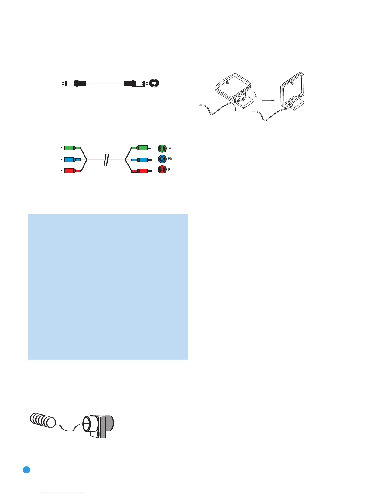
Component video separates the video signal into three components –
one luminance (“Y”) and two sub-sampled color signals (“Pb” and “Pr”) –
that are transmitted using three separate cables. The “Y” cable is color-
coded green, the “Pb” cable is colored blue and the “Pr” cable is
colored red. See Figure 12.
Figure 12 – Component Video
If it’s available on your video display, HDMI is recommended as the best
quality connection, followed by component video, S-video and then
composite video.
NOTES:
• Due to copy-protection restrictions, there is no output at the
Component Video Monitor Outputs for copy-protected sources.
• High-resolution 1080i and 1080p video signals are not avail-
able at the HDMI Output, but 1080i signals are passed
through, as is, to the Component Video Outputs. If your
source outputs analog high-resolution video, either use the
Component Video Outputs, change the output resolution of
your source device to 720p, or connect your source’s
component video outputs directly to your video display.
• Due to the design of some video displays, analog 480p or
720p component video source signals may produce artifacts
when used with the
A
VR’s analog video outputs (composite,
S-video or component video). If this occurs, try changing the
Video Mode setting in the INPUT SETUP menu, or connecting
the source device’
s video output directly to your video display
.
However, for best results, we recommend that you consider
upgrading to an HDMI-capable video display.
Antennas
The AVR 347 uses separate terminals for the included FM and AM
antennas that provide proper reception for the tuner.
The FM antenna uses a 75-ohm F-connector
.
See Figure 13.
Figure 13 – FM
Antenna
The AM loop antenna needs to be assembled. Then connect the two
l
eads to the screw terminals on the receiver. See Figure 14.
Figure 14 – AM Antenna
RS-232 Serial Port
The RS-232 serial port on the AVR 347 is used only for data. If
Harman Kardon releases a software upgrade for the receiver’s operating
system at some time in the future
, the upgrade may be downloaded
to the
AVR using this port. Complete instructions will be provided at
that time.
Audio Connections
Left Right
Front (FL/FR)
Center (C)
Surround (SL/SR)
Subwoofer (SUB)
Digital Audio Connections
Coaxial
Optical Output Input
Video Connections
Component Y Pb Pr
Composite
S-Video
S-video cable
 Loading...