Do you have a question about the Harman Kardon AVR 350/230 and is the answer not in the manual?
| HDMI Inputs | 3 |
|---|---|
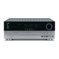
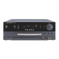
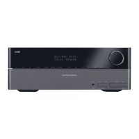
| Type | AV Receiver |
| Input Sensitivity | 200mV |
| Signal to Noise Ratio | 100dB |
| Total Harmonic Distortion | 0.07% |
| Speaker Impedance | 8 Ohms |
| Audio Formats Supported | Dolby Digital, Dolby Digital EX, DTS, DTS-ES, DTS Neo:6 |
| Input Impedance | 47 kΩ |
| Frequency Response | 10Hz - 100kHz (+/- 3 dB) |
Important safety precautions to be followed during servicing and component replacement.
Details on audio modes, power output, input sensitivity, and frequency response.
Specifications for FM/AM tuners, video formats, and frequency response.
Details on power requirements, dimensions, and weight of the unit.
List and visual representation of included manuals and accessory items.
Diagram illustrating the contents of the product packaging.
Instructions for removing the top cabinet by unscrewing it from the chassis.
Instructions for removing the front panel assembly, including disconnecting cables.
Instructions for removing the rear panel by unscrewing it.
Instructions for removing the main printed circuit board assembly.
Detailed steps for removing the top cabinet and front panel assembly, including connector disconnections.
Instructions for removing the Volume PCB after disconnecting cables and connectors.
Instructions for removing the Phone PCB after disconnecting cables and connectors.
Instructions for removing the Power LED PCB after disconnecting cables and connectors.
Instructions for removing the FIP PCB after disconnecting cables and connectors.
Instructions for removing the Key PCB after disconnecting cables and connectors.
List and visual representation of included manuals and accessory items for AVR350/230.
Diagram illustrating the contents of the product packaging for AVR350/230.
Illustrated guide for removing the top cabinet, front panel, rear panel, and main PCB for AVR350/230.
Comprehensive list of electrical parts, part numbers, descriptions, and values for both models.
List of components for the front panel and bottom chassis assemblies.
List of components on the front PCB, including capacitors and connectors.
List of components on the main PCB, including motors, capacitors, and ICs.
List of components for the Input PCB assembly, including capacitors and ICs.
List of components for the Hudson PCB assembly, including capacitors and ICs.
List of components for the Power PCB assembly, including capacitors, diodes, and resistors.
List of components for the Video PCB assembly, including PCBs and capacitors.
List of components for the Hudson Jack PCB assembly.
Index and breakdown of different schematic diagram sections covering unit parts.
Schematic details for the multi-room audio and A-BUS interface sections.
Schematic details for the voltage regulator circuits.
Schematic details for the XM module, specific to USA versions.
Schematic details for the bias and transistor circuitry.
Schematic details for the digital input/output interfaces.
Schematic details for the remote control input/output circuitry.