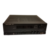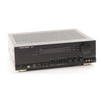
Do you have a question about the Harman Kardon AVR21 and is the answer not in the manual?
| Type | AV receiver |
|---|---|
| Channels | 5.1 |
| Total Harmonic Distortion | 0.07% |
| Input Sensitivity | 200mV |
| Speaker Load Impedance | 8 ohms |
| Input Connections | composite, coaxial, optical |
| Output Connections | composite |
| Video Connections | composite |
| Weight | 24 lbs |
Detailed technical specs for front/rear amplifier output, distortion, and sensitivity.
Technical specs for video input/output and FM reception parameters.
Technical specs for center amplifier and AM reception parameters.
Power, speaker selection, headphone jack, bass, and treble controls.
Balance control, surround mode, center mode, and test tone functions.
VCR recording, tuning, input selection, volume, loudness, display, and RDS controls.
Steps to remove the top cover, bottom cover, and front panel assembly.
Steps to remove various PC boards including volume, tone, and front panel boards.
Steps for removing speaker, tuner, surround, video, and subwoofer PC boards.
Steps to remove the chassis back, main PC board, and input PC board.
Pin assignments and block diagram of the CPU (IC401).
Description of various input/output terminal functions and pin assignments.
Explanation of the digital tuning system and key matrix assignments.
Explanation of the speaker protection circuit and its operation.
Explanation of the thermal protection circuit and its operation.
List of required equipment and identification of test points for alignment.
Procedures for aligning AM IF/RF and FM IF/RF stages.
Procedure for FM Multiplex and Stereo Modulation alignment.
Schematic diagram for Printed Circuit Board 1 (Main Board).
Schematic diagrams for Front, Tuner, Input, and Speaker boards.
Schematic diagrams for Tone, Volume, Sub-Woofer, and Video boards.
Lead identification and block diagrams for various ICs (KIA4559S, NJM2177, GD4066, etc.).
Lead identification and block diagrams for HA12016, LC7821, TA7291S, LC4966B, NJU9701, LA1266 ICs.
Wiring diagrams for Main, Input, Speaker, Front, Sub-Woofer, and Volume boards.
