EasyManua.ls Logo

Harman Kardon AVR500 User Manual

Harman Kardon AVR500
94 pages
To Next Page IconTo Next Page
Page #1 background imageLoading...
Page #1 background image
harman/kardon
AVR500
A/V DOLBY DIGITAL RECEIVER
SERVICE MANUAL
CONTENTS
SPECIFICATIONS ………………………………..…2
ESD WARNINGS…………………………………… 4
LEAKAGE TEST……………………………………. 5
CONTROLS AND FUNCTIONS……………………6
SERVICE PROCEDURE………………………….. .9
TEST EQUIPMENT REQUIRED……………… …9
ALIGNMENT PROCEDURES………………………9
ALIGNMENT AND TEST POINTS……………….. 11
CIRCUIT DESCRIPTION…………………………..13
BLOCK DIAGRAM ………………………………….16
BULLETIN HK2000-02……………..………..……..17
BULLETIN HK2000-04………………...….………..19
BULLETIN HK2000-05………………...….………..21
DISASSEMBLY PROCEDURES ………… .……23
GENERAL UNIT PARTS LIST …………………..24
GENERAL UNIT EXPLODED VIEW………..….. 26
PC . BOARDS …………………………………..…27
ELECTRICAL PARTS LIST ………………….…..32
IC BLOCK DIAGRAMS …………………….….….55
CPU PIN CONFIGURATION……………….…….75
FLT PIN CONFIGURATION………………….…. 76
SCHEMATIC DIAGRAMS ……………..…….…..83
PIN CONNECTION DIAGRAM …………….……92
WIRING DIAGRAM ………………………….……93
PACKING MATERIAL AND PARTS LIST………94
harman/kardon, Inc.
250 Crossways Park Dr.
Woodbury, New York 11797 Rev1 11/2003

Table of Contents

Question and Answer IconNeed help?

Do you have a question about the Harman Kardon AVR500 and is the answer not in the manual?

Harman Kardon AVR500 Specifications

General IconGeneral
BrandHarman Kardon
ModelAVR500
CategoryReceiver
LanguageEnglish

Summary

Specifications

Front Amp Section Specifications

Performance specifications for the front amplifier channels.

ESD Warnings and Safety Precautions

Handling Electrostatic Sensitive Devices

Precautions for handling static-sensitive electronic components.

Product Safety Notice Guidelines

General safety guidelines and component replacement precautions.

Leakage Test Procedure

Leakage Test for Service Engineers

Step-by-step guide for performing electrical leakage tests.

Controls and Functions Overview

Front Panel Controls

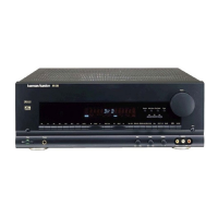
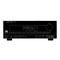
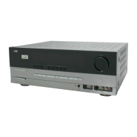
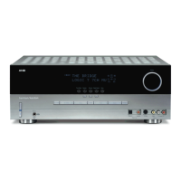
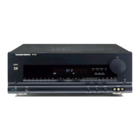
Detailed descriptions of all front panel controls.

Rear Panel Connections and Terminals

Identification and description of rear panel I/O ports.

Service Procedures

Alignment Procedures and Adjustments

Step-by-step guide for unit alignment and calibration.

Alignment and Test Points on PCBs

Identifies specific test points and alignment locations on PCBs.

Circuit Description

Block Diagrams

AVR-300/500/UL/RDS System Block Diagram

Overall system block diagram illustrating major component interactions.

Service Bulletins

Bulletin HK2000-02: DTS Mode Noise

Addresses random noise/erratic output in DTS mode.

Bulletin HK2000-04: Logic 7 Mode Noise

Addresses noise in Logic 7 mode.

Bulletin HK2000-05: Volume Level Changes

Addresses volume level changes by itself or when tapped.

Disassembly Procedures

General Unit Exploded View

Electrical Parts List

CPU Pin Configuration

Pin Description for CXP82860-180Q MCU

Detailed pin-out and function of the main microcontroller.

CPU Pin Assignment Grid

Pin assignment grid for the receiver's CPU.

Schematic Diagrams

Main Amp P.C. Board Schematic

Detailed schematic for the main amplifier circuit.

DSP P.C. Board Schematic

Schematic diagram for the digital signal processing board.

Tuner P.C. Board Schematic

Schematic diagram for the tuner section.

Wiring Diagram

Related product manuals