EasyManua.ls Logo

Harman Kardon AVR300 User Manual

Harman Kardon AVR300
91 pages
To Next Page IconTo Next Page
Page #1 background imageLoading...
Page #1 background image
harman/kardon
AVR300
A/V DOLBY DIGITAL RECEIVER
SERVICE MANUAL
CONTENTS
SPECIFICATIONS…………………..…….…..2
ESD WARNING…………………..….……… .4
LEAKAGE TESTING………………...….…....5
CONTROLS AND FUNCTIONS….…….…. .6
SERVICE PROCEDURE……………..….…..9
ALIGNMENT PROCEDURE…………….… .9
IDLE CURRENT/DC OFFSET..…………….10
ALIGNMENT/TEST POINTS………..….…. 11
CIRCUIT DESCRIPTION……………….…. 13
BLOCK DIAGRAM……………………… …16
BULLETIN HK2000-05…………..…...…. …17
BULLETIN HK2000-02 Rev1…..………..….18
DISASSEMBLY PROCEDURE…..……...…21
UNIT EXPLODED VIEW………………..…..22
MECHANICAL PARTS LIST…………..……23
PCB DRAWINGS……………………………25
ELECTRICAL PARTS LIST……………..….30
INTEGRATED CIRCUIT DRAWINGS…..…52
SCHEMATICS………………….…..……..…80
SEMICONDUCTOR PINOUTS………….…89
WIRING DIAGRAM…………………….…...90
PACKAGE………………………………..…..91
harman/kardon, Inc.
250 Crossways Park Dr.
Woodbury, New York 11797 Rev0 – 6/2002
Question and Answer IconNeed help?

Do you have a question about the Harman Kardon AVR300 and is the answer not in the manual?

Harman Kardon AVR300 Specifications

General IconGeneral
TypeAV Receiver
Input Sensitivity200mV
Signal to Noise Ratio100dB
Speaker Load Impedance8 ohms
Digital InputsCoaxial, Optical
Video ConnectionsComponent, Composite
Audio Inputs/Outputs6 In / 2 Out RCA, 7.1 Pre-Out

Summary

Product Specifications

Amplifier and Tuner Specifications

Details on front/rear amps, subwoofer, video, FM, and AM performance.

General Specifications

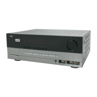
Power consumption, dimensions, weight, and other general parameters.

Safety and Testing

Electrostatic Discharge (ESD) Warning

Precautions to prevent damage from static electricity.

Leakage Test Procedure

Safety check for leakage current before user return.

Controls and Service Procedures

Front Panel Controls and Remote

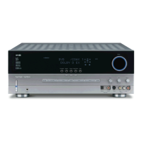
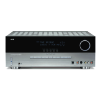
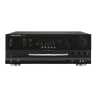
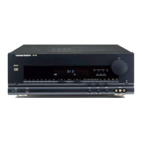
Explanation of front panel controls and remote operation.

Service Procedures and Alignment

Step-by-step procedures for alignment and adjustments.

Amplifier Adjustments

Procedures for idling current and DC offset adjustment.

Circuit Description and Diagrams

Circuitry Explanations

Details on surround, Dolby Digital, PCM, and bass management circuits.

Block and Schematic Diagrams

Overview of block diagram, PC board layouts, and schematics.

Mechanical Procedures and Parts

Disassembly and Exploded View

Steps for unit disassembly and visual component guide.

Parts Lists

Comprehensive lists of general, electrical, and PCB components.

Related product manuals