Do you have a question about the Harman Kardon AVR335 and is the answer not in the manual?
Precautions to prevent damage from static electricity when handling sensitive components.
Procedure to measure leakage current to ensure safety before returning the appliance.
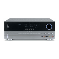
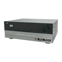
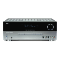
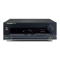
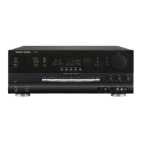
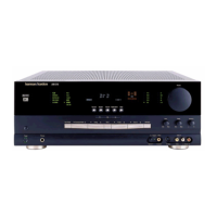
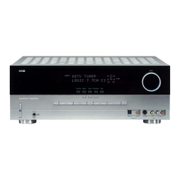
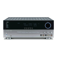
Detailed descriptions of all buttons, indicators, and connectors on the front panel.
Explanation of all input, output, and speaker connection jacks on the rear panel.
Detailed descriptions of all buttons and their functions on the remote control.
Steps for connecting audio, video, and power for system setup.
Turning the unit on/off, source selection, and volume control.
Guide to selecting and understanding various surround sound modes.
Information on digital audio sources, PCM playback, and tuner usage.
Common issues, solutions, and system memory reset procedure.
Diagram of internal components and step-by-step disassembly instructions.
Bias adjustment procedure and technical service tips.
High-level block diagrams and detailed Printed Circuit Board layouts.
Comprehensive list of electrical components with part numbers.
Datasheet for Hex Inverter IC, including pinouts and functions.
Block diagram and pin functions for the DSP processor IC.
Datasheet for the 8-channel DAC, including features and pin layout.
Datasheet for the stereo A/D Converter, covering features and pin layout.
Pin assignment and descriptions for the U-COM IC.
Block diagram and pin assignment for the microcontroller IC.
Block diagrams for common transistor and regulator IC packages.
Overall wiring diagram showing connections between major internal boards.
List and diagrams of accessories supplied with the unit.
Diagram illustrating the packaging of the unit for shipping.
| Type | AV Receiver |
|---|---|
| Amplifier Type | Discrete |
| Channels | 7.1 |
| Total Harmonic Distortion | 0.07% |
| Input Sensitivity | 200 mV |
| Input Impedance | 47k ohms |
| Tuner | AM/FM |
| Remote Control | Yes |
| Frequency Response | 10 Hz - 100 kHz |
| Signal-to-Noise Ratio | 100dB |
| Surround Sound Formats | Dolby Digital, DTS, Dolby Pro Logic II |
| Dimensions (W x H x D) | 440 x 165 x 382mm |
| Weight | 12.7kg |