EasyManua.ls Logo

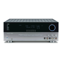
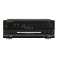
Harman Kardon AVR330 User Manual

Harman Kardon AVR330
130 pages
To Next Page IconTo Next Page
Page #1 background imageLoading...
Page #1 background image
harman/kardon
AVR330
7 X 55W 7.1 CHANNEL A/V RECEIVER
SERVICE MANUAL
CONTENTS
ESD WARNING……………………………….2
LEAKAGE TESTING……………….…..…....3
BASIC SPECIFICATIONS…………………..4
FRONT PANEL CONTROLS………..…..…..5
REAR PANEL CONNECTIONS………….…7
REMOTE CONTROL FUNCTIONS……….10
TROUBLESHOOTING GUIDE…...……..…14
PROCESSOR RESET……….……………...14
DISASSEMBLY……………….………..……15
BULLETIN HK2003-10…….........................16
TECH TIP HKTT2004-03……………………18
TECH TIP HKTT2003-01……………..…….22
UNIT EXPLODED VIEW…………………....23
BLOCK DIAGRAM……………….…………24
AMP BIAS ADJUSTMENT………………....25
PCB DRAWINGS……………….……..……27
ELECTRICAL PARTS LIST…….………….32
SEMICONDUCTOR PINOUTS………….…72
SCHEMATICS………………………………113
WIRING DIAGRAM…………………….......129
PACKAGING…………………………..……130
harman/kardon, Inc.
250 Crossways Park Dr.
Woodbury, New York 11797 Rev1 7/2005
Question and Answer IconNeed help?

Do you have a question about the Harman Kardon AVR330 and is the answer not in the manual?

Harman Kardon AVR330 Specifications

General IconGeneral
Channels7.1
Total Harmonic Distortion0.07%
Input Sensitivity200 mV
Input Impedance47 kΩ
Tuner TypeAM/FM
Inputs1 x Optical, 1 x Coaxial
Outputs2 x Composite
Weight13.2 kg
Signal-to-Noise Ratio100 dB
Dimensions165 x 435 x 390 mm

Summary

Harman Kardon AVR330 Service Manual

Safety and Precautions

Electrostatically Sensitive Devices (ES Devices)

Guidelines for handling components sensitive to static electricity.

Leakage Current Check

Procedure to measure leakage current to ensure electrical safety of the appliance.

Technical Specifications

Audio Section Specifications

Detailed specifications for the audio performance of the receiver.

Tuner Section Specifications

Specifications for the AM and FM tuner sections.

Video Section Specifications

Specifications related to the video processing capabilities.

General Specifications

General technical details including power, dimensions, and weight.

Front Panel Controls

Main Remote Control Functions

Troubleshooting Guide

Processor Reset Procedure

Procedure to reset the AVR 330's system memory to factory defaults.

Disassembly Instructions

Removal of Top Cover

Steps for removing the top cover of the unit.

Removal of Front Panel

Procedure for detaching the front panel assembly.

Service Bulletin H/K2003-10: Volume Level Changes

Tech Tip HKTT2004-03: Isolating Audio Problems Using 6/8 Direct In

Tech Tip HKTT2003-01: Backup Memory Issues

Exploded View

Amplifier Section Bias Adjustment

Electrical Parts List

Integrated Circuit Information

Transistor and IC Block Diagrams

Block diagrams for various transistors and integrated circuits.

NJM2581 Operational Amplifier Datasheet

Detailed information for the NJM2581 operational amplifier IC.

S3C84BB/F84BB Microcontroller Pin Descriptions

Pin assignment and functional descriptions for the S3C84BB/F84BB microcontroller.

Board Schematics

Main Board 1 (Amplifier) Schematics

Schematic diagram for the main amplifier board.

Video Board Schematics

Schematic diagram for the video processing board.

Front Board Schematics

Schematic diagram for the front panel interface board.

Main Board 2 (Bias & Regulator) Schematics

Schematic diagram for bias and regulator circuits.

Input Board 1 (Analog) Schematics

Schematic diagram for the analog input board.

Input Board 2 (Digital) Schematics

Schematic diagram for the digital input board.

Wiring Diagram

Instruction Manual and Package Contents

Instruction Manual and Accessories

Details of the included instruction manual and accessories.

Package Drawing

Diagram illustrating the packaging and contents of the product.

Related product manuals