EasyManua.ls Logo

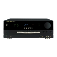
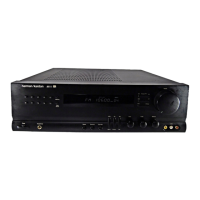
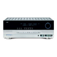
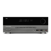
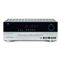
Harman Kardon AVR125 User Manual

Harman Kardon AVR125
83 pages
To Next Page IconTo Next Page
Page #1 background imageLoading...
Page #1 background image
harman/kardon
AVR125
A/V DOLBY DIGITAL RECEIVER
SERVICE MANUAL
CONTENTS
ESD WARNING………………………….…….2
LEAKAGE TESTING……………….....……....3
BASIC SPECIFICATIONS…………….….…..4
FRONT PANEL CONTROLS………………...5
FRONT PANEL DISPLAY…………………….7
REAR PANEL CONNECTIONS……..….……9
REMOTE CONTROL FUNCTIONS……..…..11
INSTALLATION AND CONNECTIONS….....14
TROUBLESHOOTING GUIDE…………..….16
MICROPROCESSOR RESET……….…..….16
UNIT EXPLODED VIEW………….…..……..17
DISASSEMBLY PROCEDURE..………….18
AMPLIFIER BIAS ADJUSTMENT……...…21
BLOCK DIAGRAM………………………….22
IC PINOUTS……………………………..….23
TRANSISTOR PINOUTS………..…..…….52
ELECTRICAL PARTS LIST………..…..….53
PCB DRAWINGS……………………..……62
SCHEMATICS…………………………...…70
WIRING DIAGRAM..……………………….82
PACKAGING………..…………………...…83
harman/kardon, Inc.
250 Crossways Park Dr.
Woodbury, New York 11797 Rev5 2/2005
Question and Answer IconNeed help?

Do you have a question about the Harman Kardon AVR125 and is the answer not in the manual?

Harman Kardon AVR125 Specifications

General IconGeneral
TypeAV Receiver
Channels5.1
Total Harmonic Distortion0.07 %
Frequency Response20 Hz - 20 kHz
Input Sensitivity200 mV
Weight12.2 kg
Tuning rangeFM/AM
Digital inputs2 optical, 1 coaxial
Video inputs3 composite, 1 S-Video

Summary

Safety Precautions

Electrostatic Discharge (ESD) Device Handling

Guidelines for handling sensitive electronic components to prevent static damage.

Leakage Current Check Procedure

Essential safety check to measure leakage current to earth ground before returning to customer.

Front Panel Interface

Rear Panel Connections

Remote Control Operation

Installation and Troubleshooting

System Installation and Connections

Step-by-step guide for connecting audio and video equipment to the AVR125.

Troubleshooting Common Issues

Guide to diagnosing and resolving common operational problems with the AVR125.

Service Procedures and Diagrams

Exploded View and Parts List

Visual breakdown of unit components and a comprehensive list of replacement parts.

Amplifier Bias Adjustment

Procedure for adjusting the bias voltage and current in the amplifier section.

Electrical Parts Lists

PCB Layouts, Schematics, and Wiring

PCB Layout Diagrams

Layout diagrams for various PCBs, showing component placement and routing.

Schematic Diagrams

Detailed circuit schematics for the AVR125's internal electronics.

Related product manuals