EasyManuals Logo

Harman Kardon AVR125 User Manual

Harman Kardon AVR125
83 pages
To Next Page IconTo Next Page
To Previous Page IconTo Previous Page
Page #21 background imageLoading...
Page #21 background image
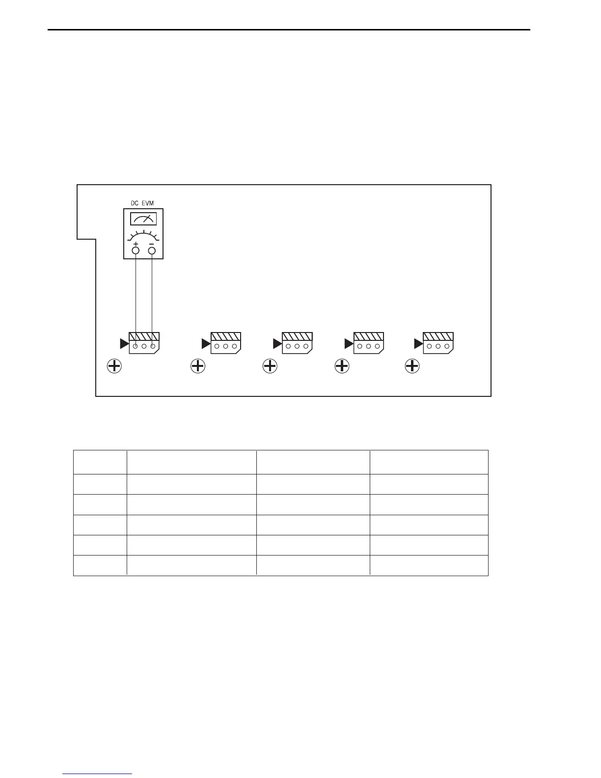
AMPLIFIER SECTION BIAS ADJUSTMENT
CUP11517X (MAIN PCB)
Measurement condition
. No input signal or volume position is minimum.
Standard value.
. Ideal current = 48mA ( ± 5%)
. Ideal DC Voltage = 21.12mV ( ± 5%)
DC VOLTMETER..............Connect to CN61, CN62, CN63, CN64, CN65
NO. Channel Adjust for
Adjustment
1 Front Left 21.12mV (±5%)
VR61
CN61
VR61
2 Front Right 21.12mV (±5%)
21.12mV (±5%)
21.12mV (±5%)
21.12mV (±5%)
VR62
CN62
VR62
3 Center
VR63
CN63
VR63
4 Surround Left
VR64
CN64
VR64
5 Surround Right
VR65
VR65
CN65
21
AVR125
harman/kardon

Questions and Answers:

Question and Answer IconNeed help?

Do you have a question about the Harman Kardon AVR125 and is the answer not in the manual?

Harman Kardon AVR125 Specifications

General IconGeneral
BrandHarman Kardon
ModelAVR125
CategoryReceiver
LanguageEnglish

Related product manuals