AVR125/225 DISASSEMBLY PROCEDURE
<1> TOP-CABINET(21) REMOVAL
1. Remove 13 screws(S1,S7) and then remove the Top-cabinet.
<2> FRONT PANEL ASS’Y REMOVAL
1. Remove the Top-cabinet, referring to the previous step<1>.
2. Disconnect the connect (BN72-Card canle)) on the FP PCB(37-1) from connector(CN72) on the Input PCB(39-1)
3. Disconnect the lead wire(BN80-8P) on the FP PCB(37-1) from connector(CN80) on the Main PCB(38).
4.Disconnect the lead wire(BN16-8P,BN10-4P) on the Tone PCB(37-3) from connector(CN16,CN10) on the Connect
PCB(37-7).
5. Disconnect the lead wire(BN41-6P) on the Tone PCB(37-3) from connector(CN41) on the Video PCB(39-2).
6. Disconnect the lead wire(BN18-5P) on the Digital input PCB(37-8) from connector(CN18) on the Input PCB(39-1).
7. Disconnect the lead wire(BN81-6P,BN83-2P) on the FP PCB(37-1) from connector(CN81.CN83) on the
Trans PCB(39-3).
8. Disconnect the lead wire(BN88-2P) on the Main PCB(38) from connector(CN88) on the Moms PCB(37-5).
9. Remove 1 screw(S10) and then lead wire(JW82-2P) on the Phone PCB(37-4).
10. Remove 9 screws(S1) and then remove the Front Panel ASS’Y.
<3> TONE PCB(37-3) REMOVAL
1. Remove the Top-cabinet, referring to the previous step<1>.
2. Remove the Front Panel ASS’Y, referring to the previous step<2>.
3. Pull out the Volume Knob ASS’Y & 3 Rotary Knobs(5).
4. Remove 1 Nut(40), 1 Washer(41)
5. Remove 7 screws(S2) and then remove the Tone PCB(37-3).
6. Disconnect the lead wire(BN84-5P,BN90-2P) One the Tone PCB(37-3) from connector(CN84,CN90) on the
FP PCB(37-1)
7. Disconnect the lead wire (BN87-6P) One the Tone PCB(37-3) from connector(CN87) on the Phone PCB(37-4)
<4>PHONE PCB(37-4) REMOVAL
1. Remove the Top-cabinet, referring to the previous step<1>.
2. Remove the Front Panel ASS’Y, referring to the previous step<2>.
3. Disconnect the lead wire (BN87-6P) One the Tone PCB(37-3) from connector(CN87) on the Phone PCB(37-4)
4. Remove 2 screws(S2,S3) and then remove the Phone PCB(37-4)
.
<5>POWER LED PCB(37-6) REMOVAL
1. Remove the Top-cabinet, referring to the previous step<1>.
2. Remove the Front Panel ASS’Y, referring to the previous step<2>.
3. Remove 2 screws(S2) and then remove the Power led PCB(37-6).
4. Disconnect the lead wire(BN88-4P) from connector(CN88) on the FP PCB(37-1).
<6>FRONT PCB(37-1) REMOVAL
1. Remove the Top-cabinet, referring to the previous step<1>.
2. Remove the Front Panel ASS’Y, referring to the previous step<2>.
3. Remove the Tone PCB(37-3), referring to the previous step<3>.
4. Remove the Phone PCB(37-4), referring to the previous step<4>.
5. Remove the Power led PCB(37-6), referring to the previous step<5>.
6. Remove 6 screws(S2) and then remove the Front PCB(37-1)
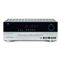
AVR125
harman/kardon
 Loading...