<7>TUNER MODULE(40) REMOVAL
1. Remove the Top-cabinet, referring to the previous step<1>.
2. Disconnect the connector(CON1-Card cable) from connector(CN13) on the Input PCB ASS’Y(39-1).
3. Remove 2 screws(S8) and then remove the Tuner Module(40).
<8>VIDEO PCB(39-2) REMOVAL
1. Remove the Top-cabinet, referring to the previous step<1>.
2. Disconnect the lead wire(BN41-6P) on the Tone PCB(37-3) from connector(CN41) on the Video PCB(39-2).
3.Disconnect the connector (CN15-Card cable) on the Input PCB(39-1) from lead wire(CN43) on the Video PCB(39-2).
4. Remove 6 screws(S8) and then remove the Video PCB(39-2).
<9>INPUT PCB(39-1) REMOVAL
1. Remove the Top-cabinet, referring to the previous step<1>.
2. Remove the Connect PCB(37-7).
3. Disconnect the lead wire(BN18-5P) on the Digital input PCB(37-8) from connector(CN18) on the Input PCB(39-1).
4. Disconnect the connect (BN72-Card canle)) on the FP PCB(37-1) from connector(CN72) on the Input PCB(39-1)
5. Remove 13 screws(S8,S11) and then remove the Input PCB(39-1).
<10>POWER TRANS(31) REMOVAL
1. Remove the Top-cabinet, referring to the previous step<1>.
2. Disconnect the connector (CN20,BN96) on the Trans PCB from lead wire(CN20-3P,BN96-6P) on the
Main PCB(38).
3. Remove 1 screw(S5) and then remove the Tr PCB(39-6)
4. Remove 1 screw(S5) and then remove the Bridge Diode PCB(39-8)
3. Remove 4 Trans screws(S9) and then remove the Power Trans(31).
<11>MAIN PCB ASS’Y(38) REMOVAL
1. Remove the Top-cabinet, referring to the previous step<1>.
2. Remove the Tuner module, referring to the previous step<7>.
3. Remove the Video PCB, referring to the previous step<8>.
4. Remove the Input PCB, referring to the previous step<9>.
5. Disconnect the lead wire(BN80-8P) on the FP PCB(37-1) from connector(CN80) on the Main PCB(38).
6. Disconnect the lead wire(BN88-2P) on the Main PCB(38) from connector(CN88) on the Moms PCB(37-5).
7. Disconnect the connector (CN20,BN96) on the Trans PCB from lead wire(CN20-3P,BN96-6P)
on the Main PCB(38)..
8. Remove 11screws(S1-1EA, S4-2EA, S6-2EA, S8-6EA) and then remove the Main PCB ASS’Y(38).
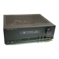
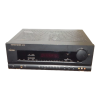
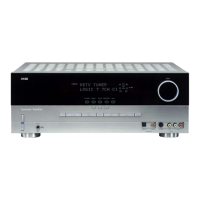
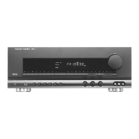
AVR125
harman/kardon

 Loading...