EasyManua.ls Logo

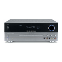
Harman Kardon AVR347 User Manual

Harman Kardon AVR347
218 pages
To Next Page IconTo Next Page
Page #1 background imageLoading...
Page #1 background image
harman/kardon
AVR347
7 X 55W 7.1 CHANNEL A/V RECEIVER
SERVICE MANUAL
CONTENTS
ESD WARNING……………………………….2
LEAKAGE TESTING……………….…..…....3
BASIC SPECIFICATIONS…………………..4
PACKAGING………………………..………..5
FRONT PANEL CONTROLS………..…..…..6
REAR PANEL CONNECTIONS………….…8
REMOTE CONTROL FUNCTIONS.………11
CONNECTIONS………………………….…14
OPERATION………………………...………33
TROUBLESHOOTING GUIDE…...……..…41
PROCESSOR RESET……………….….…..42
DISASSEMBLY………………………………43
UNIT EXPLODED VIEW……………………..48
EXPLODED VIEW PARTS LIST……………49
AMP BIAS ADJUSTMENT………………….50
BLOCK DIAGRAM…………………………..51
ELECTRICAL PARTS LIST……………..…52
PCB DRAWINGS……………………………98
SEMICONDUCTOR PINOUTS……….…..107
SCHEMATICS………………………………209
WIRING DIAGRAM...................................219
harman/kardon, Inc.
250 Crossways Park Dr.
Woodbury, New York 11797 Rev 0 6/2007
Question and Answer IconNeed help?

Do you have a question about the Harman Kardon AVR347 and is the answer not in the manual?

Harman Kardon AVR347 Specifications

General IconGeneral
BrandHarman Kardon
ModelAVR347
CategoryReceiver
LanguageEnglish

Summary

ESD Warning

Safety Precautions

Leakage Current Check

Procedure to measure leakage current to ensure user safety.

AVR 347 Technical Specifications

Front Panel Controls

Rear Panel Connections

HDMI Inputs and Output

HDMI ports for digital audio and video signal transmission.

Main Remote Control Functions

Connections

Speaker Connections

Details on connecting speakers using binding posts and different wire types.

Digital Audio

Explanation of coaxial, optical, and HDMI digital audio connections.

Video Connections

Overview of composite, S-video, component, and HDMI video connections.

Installation

Step One – Connect the Speakers

Instructions for connecting speakers to the receiver's terminals.

Step Four – Connect the Source Components

Guidance on connecting various audio/video source devices.

Step Five – Connect Video Display

Connecting the receiver's video outputs to the display device.

Step Eight – Program Sources Into the Remote

Process for programming the remote to control various source devices.

Initial Setup

Configure the AVR 347 Using EzSet/EQ

Guide to using the automatic speaker calibration system.

Configure Sources

Assigning audio/video inputs to specific source devices.

Operation

Troubleshooting Guide

Processor Reset

Processor Reset

Factory reset procedure for the AVR 347 unit.

Disassembly

AMPLIFIER SECTION BIAS ADJUSTMENT

AVR347 Electrical Parts List

Wiring Diagram

Related product manuals