18
2
Models: AVR300, AVR500 Subject: Random Noise, Erratic Output in DTS Mode
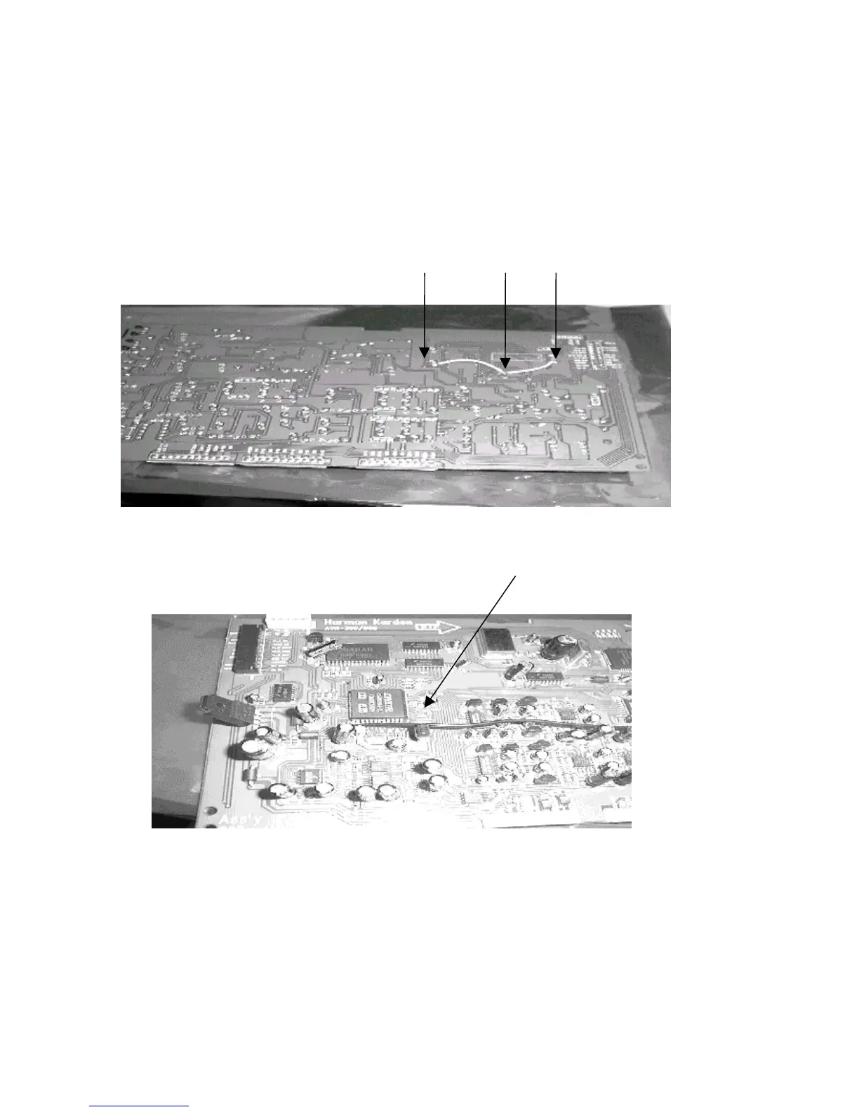
9) Ground Reinforcement:
Using an insulated 16AWG wire, Connect Negative sides of the following capacitors on the bottom side of the
PCB as shown below. Negative side of each cap will have a white mark on the component side of the PCB.
A. Negative polarity of C746 Elec Cap (1uF/50V) in the proximity of ROM IC709
B. Negative polarity of C749 Elec Cap (1uF/50V) in the proximity of IC708 DSP IC
C. Negative polarity of C744 Elec Cap (1uF/50V) in the proximity of IC710 74VHC574
C B A
10) Replace:
R756 & R755. Original parts may be 600W resistors, or Capacitors. Change both to 33W 1/10W
SMD resistors (h/k part#
292-33.2). See location below.
11) Replace DSP PC Board back into its (3) receptacle plugs atop the MAIN PCB.
12) Replace all screws, braces, and any cable ties that were cut during disassembly. Before tightening the
screws, make sure all PCB’s and their RCA jacks are firmly seated in their respective holes in the rear
backplate. If using a power tool, use care and minimum effort to avoid damaging the various plastic
receptacles.
13) Plug both the 22 conductor ribbon cable and the 5 conductor molex cable back into their receptacles.
14) Replace the top cover and optical plugs.
15) Test unit by powering up the receiver and playing a source with DTS encoded material; confirm the complaint
of Random Noise or Erratic Output is no longer occurring.

 Loading...