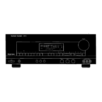
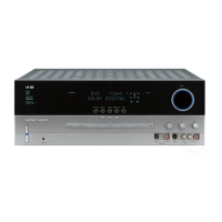
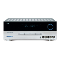
EasyManua.ls Logo

Harman Kardon AVR7000 User Manual

Harman Kardon AVR7000
104 pages
To Next Page IconTo Next Page
Page #1 background imageLoading...
Page #1 background image
harman/kardon
AVR7000
A/V DOLBY DIGITAL RECEIVER
PRELIMINARY
SERVICE MANUAL
CONTENTS
ESD WARNING…………………..….……….2
LEAKAGE TESTING………………...….…....3
BASIC SPECIFICATIONS……………….…..4
DETAILED SPECIFICATIONS………….…..5
FRONT PANEL CONTROLS………….…..13
REAR PANEL CONNECTIONS……..….…15
REMOTE CONTROL FUNCTIONS……….17
SERVICE BULLETINS/TECH TIPS…...20
IDLE CURRENT ADJUST………………...23
TUNER ALIGNMENT………………….…..24
TROUBLESHOOTING GUIDE...…….…27
UNIT EXPLODED VIEW…………………..28
EXPLODED VIEW………………………….29
BLOCK DIAGRAM…………………………30
PCB DRAWINGS……………………..……31
MECHANICAL PARTS LIST………………47
ELECTRICAL PARTS LIST……………….67
SCHEMATICS………………….…..………70
WIRING DIAGRAM………………………...94
PACKAGE…………………………………..95
harman/kardon, Inc.
250 Crossways Park Dr.
Woodbury, New York 11797 Rev1 – 11/2000
All manuals and user guides at all-guides.com
all-guides.com

Other manuals for Harman Kardon AVR7000

Question and Answer IconNeed help?

Do you have a question about the Harman Kardon AVR7000 and is the answer not in the manual?

Harman Kardon AVR7000 Specifications

General IconGeneral
TypeStereo receiver
Weight21.1 kg
Input Impedance47 kOhms
Frequency Response20Hz - 20kHz
Input Sensitivity200mV
Signal to Noise Ratio100dB
Total Harmonic Distortion0.07% (stereo)

Summary

Electrostatic Discharge (ESD) Precautions

Product Safety Notice

Leakage Test Procedure

Technical Specifications Overview

Tuner Section Specifications

Digital (AC-3) Section Specifications

Front Panel Controls Overview

Rear Panel Connections Diagram

Main Remote Control Functions

Service Bulletin: Video Signal Color Shift

Service Bulletin: Switched AC Accessory Outlet Dead

Troubleshooting Tip: Remote Control Issues

Idle Current Adjustment Procedure

Tuner Alignment Procedure

Troubleshooting Guide

Processor Reset Procedure

How to perform a system memory reset on the AVR7000.

Block Diagram

Exploded View Parts List

Mechanical Parts List

Electrical Parts List (General)

Schematic Diagram: Power Amplifier (2-Channel)

Schematic Diagram: Power Amplifier (3-Channel)

Schematic Diagram: Digital Signal Processing

Schematic Diagram: Main Board

Schematic Diagram: Tuner Section

Wiring Diagram

Packing Diagram

Related product manuals