EasyManua.ls Logo

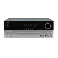
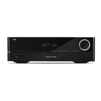
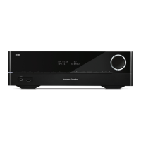
Harman Kardon AVR137 User Manual

Harman Kardon AVR137
87 pages
To Next Page IconTo Next Page
Page #1 background imageLoading...
Page #1 background image
harman/kardon Service Manual
AVR137/230
5 x 30W 5.1 CHANNEL A/V RECEIVER
CONTENTS
ESD WARNING……………………..…..2 ELECTRICAL PARTS LIST…….……12
LEAKAGE TESTING……………….....…..3 SEMICONDUCTOR PINOUTS……...35
BASIC SPECIFICATIONS…………….….4 PCB DRAWINGS………….................72
TROUBLESHOOTING GUIDE….…….....5 BLOCK DIAGRAM……...................78
PROCESSOR RESET………….……5 WIRING DIAGRAM…….....................79
PACKAGE LIST AND PARTS……….…...6 AMP BIAS ADJUSTMENT….…....…..80
DISASSEMBLY……………………….…7 SCHEMATIC DIAGRAMS……………81
UNIT EXPLODED VIEW AND PARTS...11
Released EU2008 harman/kardon, Inc. Rev 0, 04/2008
250 Crossways Park Dr.
Woodbury, New York, 11797
Page 1 of 87
All manuals and user guides at all-guides.com
all-guides.com
Question and Answer IconNeed help?

Do you have a question about the Harman Kardon AVR137 and is the answer not in the manual?

Harman Kardon AVR137 Specifications

General IconGeneral
Number of Channels5.1
TypeAV Receiver
Total Harmonic Distortion0.07%
Frequency Response10Hz - 100kHz
Input Sensitivity200mV
HDMINo
TunerAM/FM
Digital audio inputCoaxial
Video InputComposite, S-Video
Signal to Noise Ratio100dB

Summary

Electrostatically Sensitive Devices

Product Safety Notice

Important safety notices and component identification for servicing.

Safety Precautions

Leakage Current Check

Procedure to measure leakage current to earth ground to ensure safety.

Technical Specifications

Audio Section Specifications

Specifications for audio performance including power output.

FM Tuner Section Specifications

Specifications for FM tuner performance.

AM Tuner Section Specifications

Specifications for AM tuner performance.

Video Section Specifications

Specifications for video input/output characteristics.

General Specifications

General specifications like power requirement and dimensions.

Troubleshooting Guide

Processor Reset Procedure

Procedure to reset the unit's memory and microprocessor.

Accessories and Package Contents

Disassembly Overview

Top Cabinet Removal

Step-by-step instructions for removing the top cabinet.

Front Panel Removal

Step-by-step instructions for removing the front panel assembly.

Rear Panel Removal

Step-by-step instructions for removing the rear panel.

Main PCB Removal

Step-by-step instructions for removing the main PCB.

Disassembly Procedures (Part 1)

Top Cabinet Removal Procedure

Procedure to remove the top cabinet by unscrewing.

Front Panel Assembly Removal

Procedure to remove the front panel assembly, including disconnections.

Volume PCB Removal

Procedure for removing the volume PCB.

Phone PCB Removal

Procedure for removing the phone PCB.

Disassembly Procedures (Part 2)

Power LED PCB Removal

Procedure for removing the power LED PCB.

FIP PCB Removal

Procedure for removing the FIP PCB.

Tuner Module Removal

Procedure for removing the tuner module.

Disassembly Procedures (Part 3)

Video PCB Removal

Procedure for removing the video PCB.

Input PCB Removal

Procedure for removing the input PCB.

Power Trans & Power PCB Removal

Procedure for removing the power transformer and PCB.

Main PCB Assembly Removal

Procedure for removing the main PCB assembly.

Exploded View and Parts Identification

Electrical Parts List

Wiring Diagram

Amplifier Section Bias Adjustment

Schematic Diagram (AVR132)

Main Schematic Diagram

Sub-Section Schematic Diagrams

Input/Output Schematic Diagram

Option Module Schematic Diagrams

Amplifier Sections Schematic Diagram

PCB Block Schematic Diagrams

Related product manuals