9
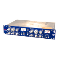
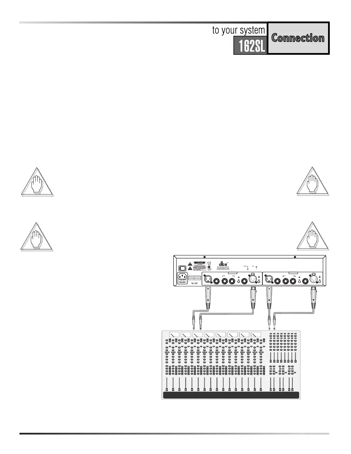
The 162SL is connected for operation using the rear panel XLR or 1/4” connectors. Note that the two
rear panel input sections have a push-switch which lifts the contact on pin #1 (ground). Keep this switch
in the OFF position (pin #1 connected) until all connections are made. Be sure that your input and out-
put cables are wired in the “pin 2/tip” configuration, which is printed on the rear panel of the 162SL.
For more information on other types of connections, refer to the section entitled Operating Notes.
When connecting the 162SL, refer to the following steps:
• Turn OFF all equipment BEFORE making any connections.
• Mounting the 162SL
The 162SL requires a two rack-space height (3.5 inches) and a standard
19 inch rack-space width. It can be mounted above or below (leaving
1U of space above and below the unit) anything that doesn’t create
excessive heat. This is to ensure proper ventilation. Ambient tempera-
tures should not exceed 113°F (45°C) when equipment is powered.
Caution:
Never remove the cover. There are no user serviceable parts inside.
• Make connections via XLR or 1/4” connectors.
• Plug in AC power cable and power ON the unit.
Note:
Check the line voltage printed on the rear panel of the 162SL and verify that
it is correct for your area.
Two Basic Compressor Setups:
A: Channel One shows processing of a
group/aux on the console.
B: Channel Two shows connections for
processing a signal from a single chan-
nel. Input of the 162SL is fed by the
channel insert output/send, and returns
to the console via the insert
input/return.
Connections
 Loading...