8
3-90-07205R26_10/14
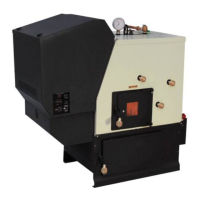
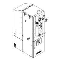
Refer to the illustration under “Parts Locations” in this
manual to identify the components listed below:
1.Installthecontrolboardcoveraswellastheaccesscover
locatedonthefeedercover.
2. Install the spring handles provided with the unit on
the ash door, firebox door and the heat exchanger
cleanoutrodhandles.(Fastenhandlesbyturningthem
counterclockwiseandpushinginwardsimultaneously).
3.Install3/4”MPTboilerdraininthettingasshown.
Note: Use pipe thread sealant or Teon tape on ALL
threads before connections are made.
4.Install3/4”MPTpressurereliefvalveasshown.
5.Installthe1/2”MPTaquastatwellinttingasshown,then
placeaquastatinthewellandfastenwithaziptie.The
aquastat sensor is located under the top sheet metal
jacket.
6.Installthe1/2”MPTtemperature/pressuregaugeintting
asshown.
7.Locateandinstalloutsideairtemperaturesensor.Location
ofthissensorshouldbeonthenorthsideofthehomeor
buildingandoutofdirectsunlight.Usethecablesupplied
withtheboilertoattachthesensortotheterminalslocated
onthehopper.(Placeatthebacksidejustaboveandto
therightofthemainpowerconnectionbox)Thewirescan
beconnectedtothesensorwiththeconnectorssupplied.
Wirenutorbuttspliceconnectorscouldalsobeused.The
connectionsattheboilercanbedonewiththetwo1/4”
femalepushonconnectorssupplied.
8. Fasten the conduit to the ash base with the clamps
provided.
Design:
Therstthingthatneedstobedoneisdecidingwhereand
howtheboilerwillbeinstalled.
Things that need to be taken into consideration are the
intendeduseoftheboilerforexample,istheboilergoingtobe
usedasyourprimaryheatingsystemorisitgoingtobeused
asasecondaryorbackupheatingsystem.Ifitistobeused
inconjunctionwithanexistingoilorgasboilersystemwillit
bepipedinparallelorinseries?Theanswerstotheseand
otherquestionscanbedeterminedbytalkingtoyourcertied
dealeroraqualiedHVACorplumbingcontractor.Thiswill
ensurethattheboilerisinstalledandpipedtoaccommodate
yourneedsandexpectations.
Consideration must be given to the venting as well as
electricalandclearancerequirements.(Clearancesmustbe
maintainedtocombustiblesandalsoforservice)
Makesurefansarenotusedinthefuelstoragearea,unless
theyareinstalledsoasnottocreateanegativepressurein
theroomwherethesolidfuelburningapplianceislocated.
Assembly
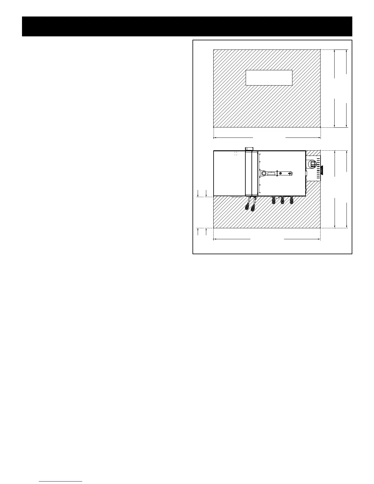
Floor Protection:
The striped area indicates the minimum required floor
protection area if the boiler is going to be placed on a
combustibleoor.Itrequires40”X55”(US)or42”X55”(CAN)
ofnoncombustibleoorprotectionasshown.16”(US)or
18”(CAN)oftheoorprotectionmustbeinfrontoftherebox
doorasshown.Floorprotectionmustbeaminimumof26
gaugesheetmetal.Floorprotectionmustalsobeprovided
underanyhorizontalrunofventpipeequaltotheoutside
diameteroftheventingplus2”toeachside.
Example: 4” type “L” or “PL” vent pipe has an outside
diameterof4-1/2”+2”oneachsideequalsaprotectedoor
areaof8-1/2”wideunderneaththehorizontalrun.
42" CANADA
18" CAN
16" USA
40" USA
55" USA & CAN
MINIMUM NON-COMBUSTIBLE FLOOR PROTECTION AREA
NON-COMBUSTIBLE
FLOOR PROTECTOR
55" USA & CAN
42" CANADA
40" USA
 Loading...