7
3-90-07205R26_10/14
Assembly
Boiler Kit Materials: (Refer to “Parts Locations” section
in this manual)
Listofitemscontainedwithintheboilerkitshippedwiththe
unit.
1-Controlboardcover
1-Accesscover(HopperSwingPlateKnob)
5-SpringHandles
1-3/4”BoilerDrain
1-3/4”SafetyReliefValve
1-1/2”AquastatWell
1-1/2”DualTemperature/PressureGauge
1-100ft.SensorCable(OutdoorAirSensor)
1-OutdoorAirSensor
1-FlueTunnelWeldment
1-CombustionBlowerAssembly
1-HeatShield(Comb.Blower)
2-UYConnectors
2-Terminals1/4Female
1-#8X1/2”TEK
3-1/4-20X5/8”WingScrew
4-1/4”LockWasher
4-1/4-20Nuts
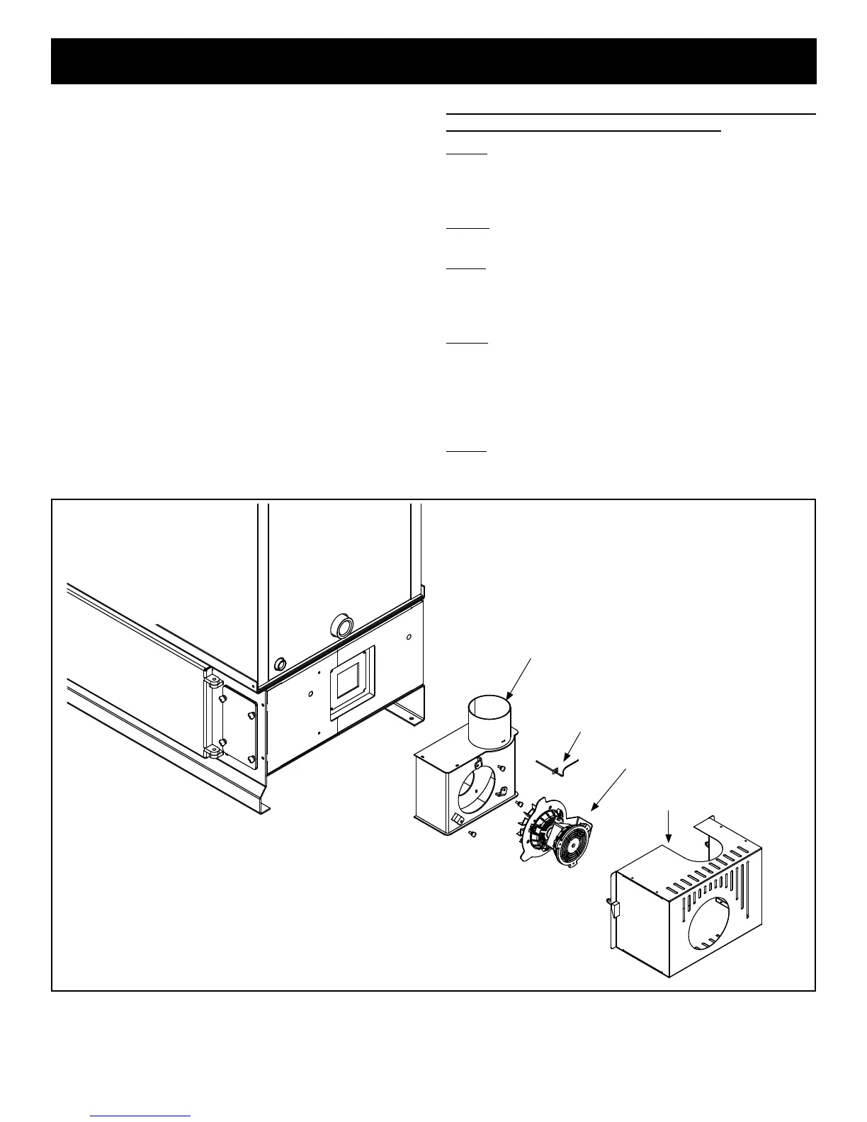
Installation of the Flue Tunnel Weldment, Combustion
Blower and Wiring, ESP and Heat Shield:
Step1:Firstinstalltheuetunnelweldmentbyaligningthe
(4)studswiththe(4)holesintheashchamberbase.Fasten
the (4) nuts and lock washers provided, to the studs by
removingtheaccesscoveronthesecondaryashchamber.
Step 2: Place the combustion motor onto the ue tunnel
weldmentandtightenthe(3)wingscrewsprovided.
Step3:InserttheExhaustSensingProbe(ESP)intothe1/8”
holeprovidedontheuepipestub.Fastenwiththe(1)#8x
1/2”TEKscrewalsoprovided.ESPwillbetapedtothesheet
metaljacketforshippingpurposes.
Step4:Connecttheexconduit90°elbow(NotShown)to
theheatshieldintheholeprovided.Thenconnectthe(3)
wiresfromthecombustionblowerwiththe(3)wiresinthe
exconduitbyusingthepush-onconnectorsandmatching
thewirecolorsasfollows:RedtoBlack,WhitetoWhiteand
GreentoGreen.
Step5:PlaceHeatShieldovercombustionblowerandalign
theswelllatcheswiththeholesinthesheetmetalandtighten.
Heat Shield
NOTE: Refer to Fig’s 22, 23, and 24 located in this manual.
Flue Tunnel Weldment
ESP
Combustion Blower
 Loading...