Date printed: 24.01.12
90
D21m System
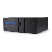
6.7.3 Air Deflector/Filter Unit A949.0599
If a D21m I/O frame has a power dissipation of less than 80 W, air deflector/
filter units should be used on top of and below the frame. For frames dissipat-
ing more power, an air deflector/filter unit should be used on top of the frame,
combined with a fan unit (see below) at its bottom. If space is available, a
second air deflector/filter unit may be used below the fan unit, increasing the
air intake cross-section and thus improving the cooling efficiency.
For more information on cooling and guidelines for power dissipation estima-
tion refer to chapter 1.2.2, paragraph ‘thermal considerations’.
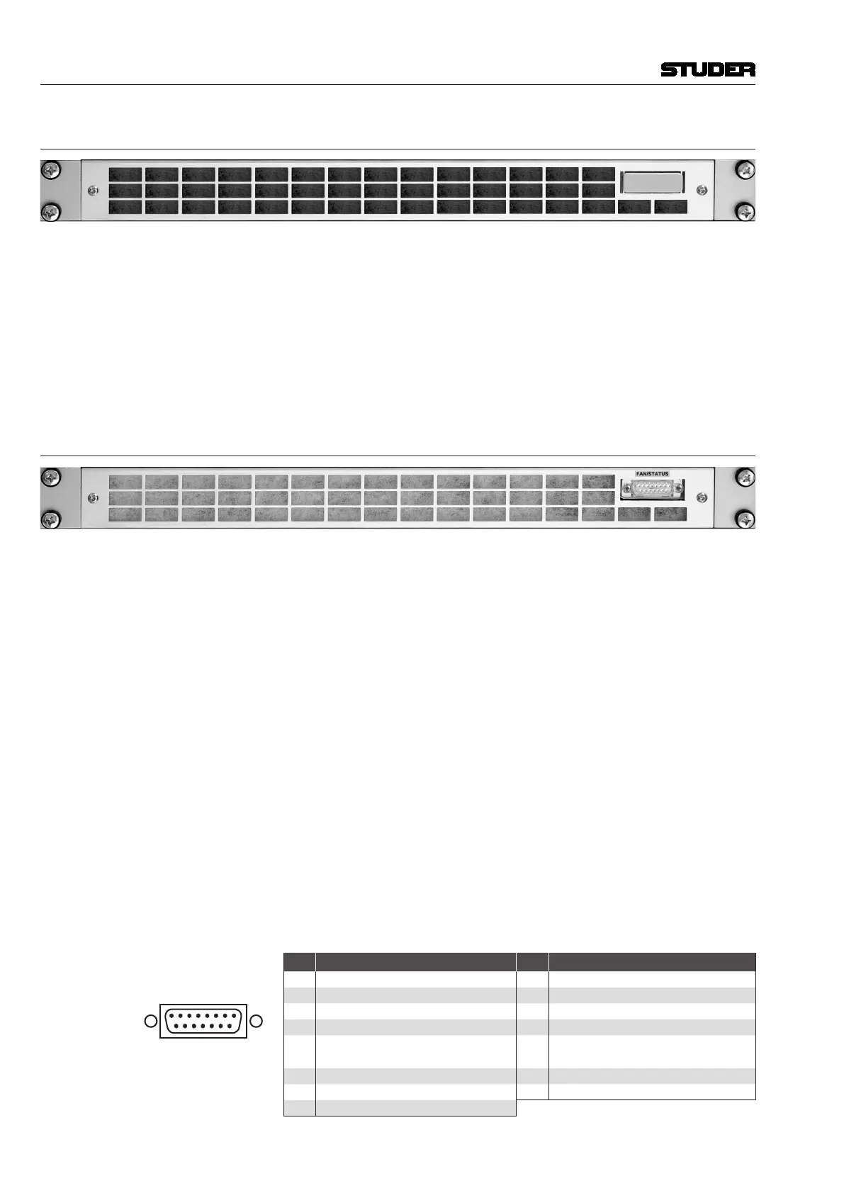
6.7.4 Fan Unit A949.0597
In cases where the power dissipation of a D21m I/O frame exceeds 80 W,
active cooling is imperative. If no cooling system for the whole rack is used,
this 1U fan unit is required underneath the D21m frame. Seven fans draw air
in from the front (filtered) and from the bottom (unfiltered) and blow it out
upward. The bottom is open and allows installing an additional air deflector/
filter unit underneath the fan unit as described above, increasing the air intake
cross-section. In most cases, however, closing the fan unit’s bottom with a
piece of metal sheet is sufficient.
For power supply to the fans and fan status monitoring, two connectors are
provided, one at the front, the second at the rear of the unit. They are con-
nected in parallel so that either one can be used, depending on the applica-
tion. If any of the fans should have a short or open circuit, the alarm signal
is triggered.
A 15-pin D-type cable (order no. C089.201167) for connection to the primary
PSU is required.
Please note that currently the fan monitoring is implemented for the use of
the fan unit within an SCore Live only.
For more information on cooling as well as guidelines for power dissipation
estimation refer to chapter 1.2.2, paragraph ‘thermal considerations’.
Pin Assignment FAN/STATUS (15pin D-type, male, UNC 4-40 thread)
9 15
Solder/Crimp View
(or Socket View)
Pin Signal Pin Signal
1 +V
cc
(+15-24 V) 9 GND
2 n.c. 10 n.c.
3 GND 11 reserved (NTC)
4 n.c. 12 n.c.
5
Alarm relay + (open collector
pulling up to V
cc
if active)
13 GND
6 n.c. 14 n.c.
7 GND 15 reserved (Alarm LED+)
8 n.c.
 Loading...