Date printed: 24.01.12
92
D21m System
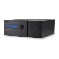
6.7.5.3 GPIO Break-Out Box A949.0588
For easier wiring of single GPI and/or GPO signals, this break-out box can
be used. 16 GPI signals and 12 of the 16 GPO signals of a GPIO card with
relay outputs (A949.0436) are wired to single, 4-pin Combicon terminals (see
below), providing the relay contacts or opto-coupler inputs, as well as GND
and a short circuit-proof 5 VDC supply.
If voltages exceeding 50 V (AC or DC) are switched, the break-out box must
be placed within a closed rack in order to avoid shock hazards by touching
the contacts!
Four of the 16 GPO signals (GPO 1-4, marked in black on the front panel) are
connected to solid-state relays whose power terminals are wired to the Com-
bicon terminals. These power contacts can switch AC loads from 24-240 V
with a maximum total current of 5 A over all 4 relays.
For safety reasons, these four terminals have no additional GND and 5 V
supply. All remaining low-voltage terminals (GPI 1-16, GPO 5-16) are coded
on pin #4 in order to prevent high-voltage connectors being inserted by mis-
take.
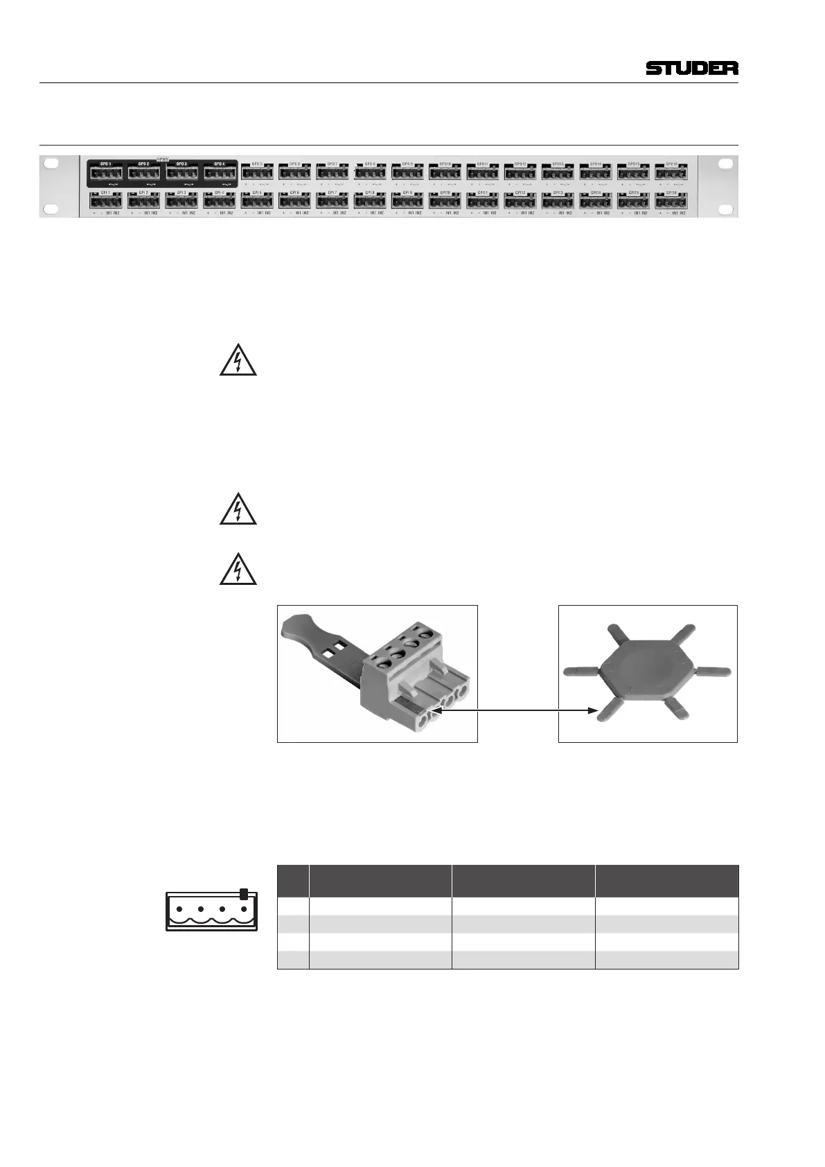
The high-voltage connectors must be coded, as shown below; six coding ele-
ments (order no. C054.251100) are included with the break-out box.
Coding Element
Eight 4-pin Combicon connectors with screw terminals (C054.251104) are
included with the break-out box. If more connectors are required, please order
separately. On the rear of the box two 37-pin D-type sockets (f) are provided
for connection to the GPIO card. For matching cables please refer to chapter
6.7.6.
Pin Assignment
*
Pin
GPO 1-4 (Outputs)
(upper row, *coded)
GPO 5-16 (Outputs)
(opper row, uncoded)
GPI 1-16 (Inputs)
(lower row, uncoded)
1 n.c. +5 V +5 V
2 n.c. GND GND
3 Power Relay, Contact 1 GPO Relay, Contact 1 Optocoupler Input 1
4 Power Relay, Contact 2 GPO Relay, Contact 2 Optocoupler Input 2
 Loading...