Date printed: 24.01.12
31
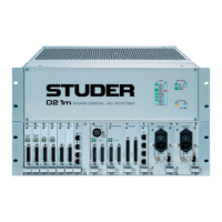
D21m System
Level Ch 1
Ch 1
Ch 3
Ch 2
Ch 4
Ch 5
Ch 7
Ch 6
Ch 8
Level Ch 3
Level Ch 5
Level Ch 7
24 dBu
15 dBu
24 dBu
15 dBu
Level Ch 2
Level Ch 4
Level Ch 6
Level Ch 8
Jumpers Level (Ch1-8) Two positions each: 15 dBu (factory default) or 24 dBu.
LEDs SIGNAL 1-8 For each of the eight channels a green LED indicates if input signal is present;
its brightness is a rough indication of the signal level.
Alignment RA1-8 The trimmer potentiometers are factory aligned for 0 dB gain of the ‘Trim’
stage in the block diagram on the left.
Set jumper to 15 dBu or 24 dBu. Feed an analog signal with a level of +6 dBu
or +15 dBu, respectively, to one of the analog inputs. Measure the level on a
digital output. Adjust the level with the corresponding LEVEL trimmer poten-
tiometer to –9 dB
FS
. If a different input sensitivity has to be adjusted, select
the desired range with the jumper and use the LEVEL trimmer potentiometer
to adjust to the desired level.
Repeat this alignment for all inputs.
Connector Pin Assignment 8× BALANCED LINE IN (25pin D-type, female, UNC 4-40 thread)
1
Solder/Crimp View
(or Socket View)
13
25
14
Pin Signal Pin Signal
1 CH 8 in + 14 CH 8 in –
2 CH 8 in GND 15 CH 7 in +
3 CH 7 in – 16 CH 7 in GND
4 CH 6 in + 17 CH 6 in –
5 CH 6 in GND 18 CH 5 in +
6 CH 5 in – 19 CH 5 in GND
7 CH 4 in + 20 CH 4 in –
8 CH 4 in GND 21 CH 3 in +
9 CH 3 in – 22 CH 3 in GND
10 CH 2 in + 23 CH 2 in –
11 CH 2 in GND 24 CH 1 in +
12 CH 1 in – 25 CH 1 in GND
13 n.c.