Date printed: 24.01.12
75
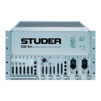
D21m System
S1
4321
ON
Default Setting:
S2
4321 8765
ON
Default Setting:
LEDs LOCK On if a valid signal is available at the input that is locked to the system clock.
DIP Switches S1
Switch Setting
1
OFF: Standard mode, 96 channels on each HD IN (factory default)
ON: Performa mode, 48 channels on each HD IN
2
OFF: Control data is passed from HD link to RS422 port (factory default);
controller connected to backplane, for use with merger
ON: Control data is passed from HD link to controller; RS422 port inactive
3
4
reserved (factory default: OFF)
S2
1 2 3 4 5 6 7 8 Setting
ON ON ON ON OFF OFF OFF OFF RS422 controller pinout (factory default)
OFF OFF OFF OFF ON ON ON ON RS422 device pinout
NO OTHER SETTINGS ALLOWED!
Connector Pin Assignments HD IN 1/2 / HD OUT 1/2 (8pin RJ45)
1
8
Socket View
Pin Signal (Input) Signal (Output)
1 Rx 0 + Tx 0 +
2 Rx 0 – Tx 0 –
3 Rx 1 + Tx 1 +
4 Rx Clk + Tx Clk +
5 Rx Clk – Tx Clk –
6 Rx 1 – Tx 1 –
7 Rx 2 + Tx 2 +
8 Rx 2 – Tx 2 –
CTRL RS422 (9pin D-type, female, UNC 4-40 thread)
1
5
9
6
Solder/Crimp View
(or Socket View)
Pin RS422 Controller RS422 Device
1 Chassis Chassis
2 RxD – TxD –
3 TxD + RxD +
4 GND GND
5 n.c. n.c.
6 GND GND
7 RxD + TxD +
8 TxD – RxD –
9 Chassis Chassis
 Loading...