Chapter 3 Electra 9200 Encoding Tutorial
© 2013 Harmonic Inc. All rights reserved. 19 Electra 9200 Release 01, Rev A
Configuring an Encoder with SDI Input and IP or ASI Output
Configuring the Output
Now that you have defined the transport stream (TS–1) that carries the service, you can assign it
to an output port/socket. In the example configuration page, the device has both GbE and ASI
output ports, as shown in Figure 3–5. Note that TS–1 is not assigned to a physic
al output yet.
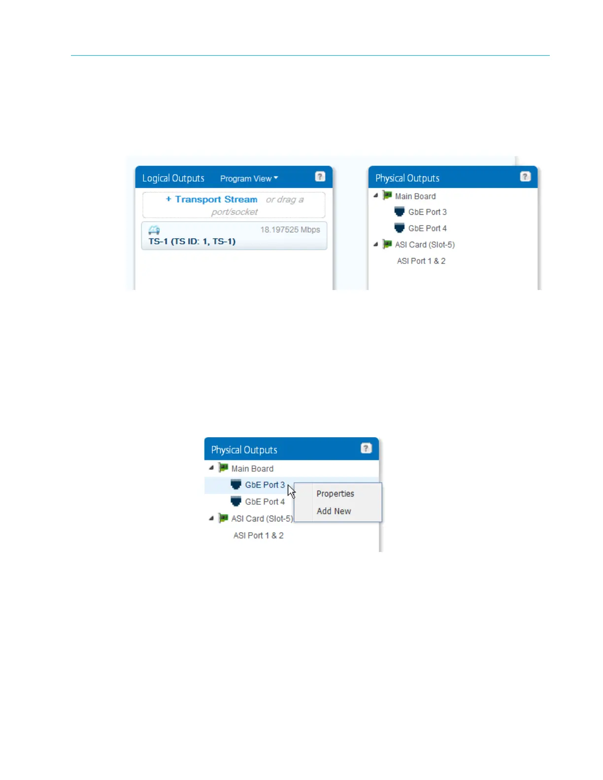
Figure 3–5: Physical Outputs
Creating an IP Socket
The Electra 9200 uses GbE ports 3 and 4 for output. In this example, we configure the GbE–Port
3, add an IP socket, then assign TS–1 to the socket.
1. In the Physical Outputs panel, expand the Main Board to display the GbE Ports as seen in
Figure 3–5.
2. First, set up the port. Right-click the
GbE–Port 3 entry and select Properties.
Provide values for the network addresses and make sure the port is enabled. Note that this is
where you set up port redundancy.