www.SteamPoweredRadio.Com
mended.
A
grounding stud is located adja-
cent to the
AC
Input terminal board.
Installation is now complete and the sta-
tion transmission line may now be con-
nected at the 7 /8 EIA flange (HT 1PM) or
N
connector (HT 250 and
SOOFM)
at the
output
of
the directional coupler.
2.2.4.
Initial Checkout
I WARNING
DISCONNECT AND LOCK OUT STATION
PRIMARY POWER TO THE TRANSMIT-
TER.
Each transmitter is thoroughly checked
out during factory final test but adjustment
may be required during installation due to
shipping, variations in primary power, an-
tenna systems, or transmission line differ-
ences.
A
20k ohm/volt multimeter (Simpson 260
or
equivalent) may be required for the
checkout.
Before proceeding with the initial
FM
Transmitter testing, ~nsure that the
FM
Ex-
citer is completely installed, all parts are
back in position and correctly wired, the
transmitter is connected to a suitable
rf
load,
and all signal monitors are connected. It is
fr
recommended that the Modulation Monitor
be connected to the BNC jack located
on
the
output side
of
the Lowpass Filter.
The complete transmitter should be in-
0
spected at this time. Use a vacuum cleaner
and thoroughly clean the interior
of
the
transmitter. Check the following:
2-2
c..--e1'hat
the primary power is connected to
the proper voltage taps but is switched
OFF.
i...-<That
the primary power is connected to
the
FM
Exciter rear plug.
LJ--That
the audio inputs are connected to
the
FM
Exciter.
........niat all connections at terminal boards
and components are tight.
---Remove any extra hardware lying within
the cabinet and tighten all nuts and bolts.
'7
"
Check relay and solenoid armature op-
, eration manually. Ensure all have free,
unobstructed movement.
• That all wires and cabling are dressed
properly and secured.
• Refer to the Factory Test Data Sheets
supplied with the transmitter and adjust
the controls
as
indicated. The transmitter
was checked into a 50-ohm resistive
load at the Factory. Therefore, any sys-
tem with a mismatch may change the
settings. In this case the recorded control
indications may not agree exactly with
actual operation.
det
the REMOTE/LOCAL switch to
LOCAL.
2.2.5. Connections to Remote Controls
The FM Transmitter may be operated by
remote control by installing a remote con-
trol system.
If
the transmitter is to be re-
motely controlled, it is important to initiate
thorough inspection and maintenance pro-
cedures at the transmitter location. Installa-
tion
of
equipment to monitor temperature
and humidity at the remote transmitter site
is also recommended. Terminations pro-
vided in the FM Transmitter allow remote
control
of
the following transmitter func-
tions by connection to terminal boards on
the controller, A 1 TB 1 and the Exciter,
A 7 A3TB 1. Complete connections to termi-
nal board
AlTBl
&/
or
A7A3TB1 are
shown in Table 2-1.
2.2.6.
External Fall-Safe Interlock Con-
nections
Remove the jumper between terminals 9
and 10 on terminal board
AlTBl
on the
Controller. Terminal board is located at the
upper rear
of
the transmitter
on
the read
of
the Controller chassis.
Connect the remote external fail-safe in-
terlock wiring to the terminals listed in the
preceding paragraph. A set
of
normally
closed contacts is required when the remote
control is operational to operate the
ac
con-
tactor circuit.
If
a separate Stereo Generator is to be
used, there is rack space directly above the
exciter provided for this equipment. The
PGM cable between the Stereo Generator
and the exciter should be no longer that 24
inches.
2.2.7. EBS Connections
Emergency Broadcast System (EBS) mut-
ing can
be
accomplished through the RF
MUTE line on the rear
of
the THE-1 Ex-
citer. This will
tum
the RF output to
OW
upon application
of
the proper signal. This
has selectable logic by jumper
A3Jl3
on the
Exciter motherboard J13 (C-1) will select
ground to mute (open collector compati-
ble). J13 (C-2) will select 2-30Vdc to mute.
Refer
to
Exciter manual for further details.
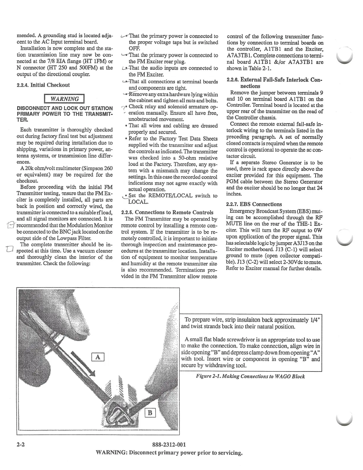
To prepare wire, strip insulaiton
back
approximately
1/4
"
and twist strands back into their natural position.
A small flat blade screwdriver is an appropriate tool to use
to make the connection. To make connection, align wire
in
side opening
"B"
and depress clamp down from opening
"A"
with tool. Insert wire
or
component in opening
"B"
and
secure
by
withdrawing tool.
Figure 2-1. Making Connections
to
WAGO Block
888-2312-001
WARNING:
Disconnect primary power prior to servicing.
 Loading...
